Heatable external mirror for motor vehicles

a rearview mirror and motor vehicle technology, applied in the direction of electric heating, ohmic resistance heating, transportation and packaging, etc., can solve the problems of not being able to recognize whether the heating system of the mirror has already been installed, the mirror pane becomes “blind”, and the led must be built into the heating circuit. to achieve the effect of improving the visual indication and improving the visual indication

Inactive Publication Date: 2007-06-12
LANG MEKRA NORTH AMERICA LLC
View PDF17 Cites 23 Cited by
  • Summary
  • Abstract
  • Description
  • Claims
  • Application Information

AI Technical Summary

Benefits of technology

[0013]In a further advantageous embodiment, the thermochromic heating indicator may be made from one of a thermochromic plastic and thermochromic foil. The thermochromic foil may be carried on one of a back side and a front side of the mirror pane. In one embodiment, the thermochromic foil is placed in heat conducting contact with the heating element within the housing and extends out of the housing to provide the visual indication. In a further embodiment, the thermochromic plastic is formed as an optical enhancing structure placed on a front side of the mirror pane to improve the visual indication.

Problems solved by technology

As a result of the mirror heating system or the heating element being switched on and off automatically by the thermostatic switch, the driver of a vehicle equipped with one or several of these mirrors may often find it difficult to recognize whether the mirror heating system has already been automatically switched on or not.
What often occurs is that the mirror pane becomes “blind” due to condensation, etc., while the thermostatic switch has however not yet switched on because the temperature for this may not yet be low enough for it.
Also, the thermostatic switch may have switched on just before checking the visibility of the mirror but no result is yet visible in the short time since the moment of being switched on because the mirror pane could not yet be heated up sufficiently.
In such cases the mirror heating system is then usually switched on manually by the driver, but this additional action by the driver is often unnecessary in instances when the thermostatic switch has switched on just before checking the visibility conditions of the mirror, while no results are yet visible because the mirror pane could not yet be heated up sufficiently.
The disadvantage of this is that the LED must be built into the heating circuit.
Because of different heating currents when using PTC elements as heating system, this results in excessively different influences on the LED and thereby different degrees of lightness.
In addition, this LED does not indicate the effectiveness of the mirror heating system but merely its operation.
In cases of a short-circuit in the surface heating element, the LED lights up even thought the functionality of the mirror heating system is insufficient.
In addition, retrofitting existing mirror systems with such technology is difficult.

Method used


Image

  • Heatable external mirror for motor vehicles
  • Heatable external mirror for motor vehicles
  • Heatable external mirror for motor vehicles

Examples


second embodiment

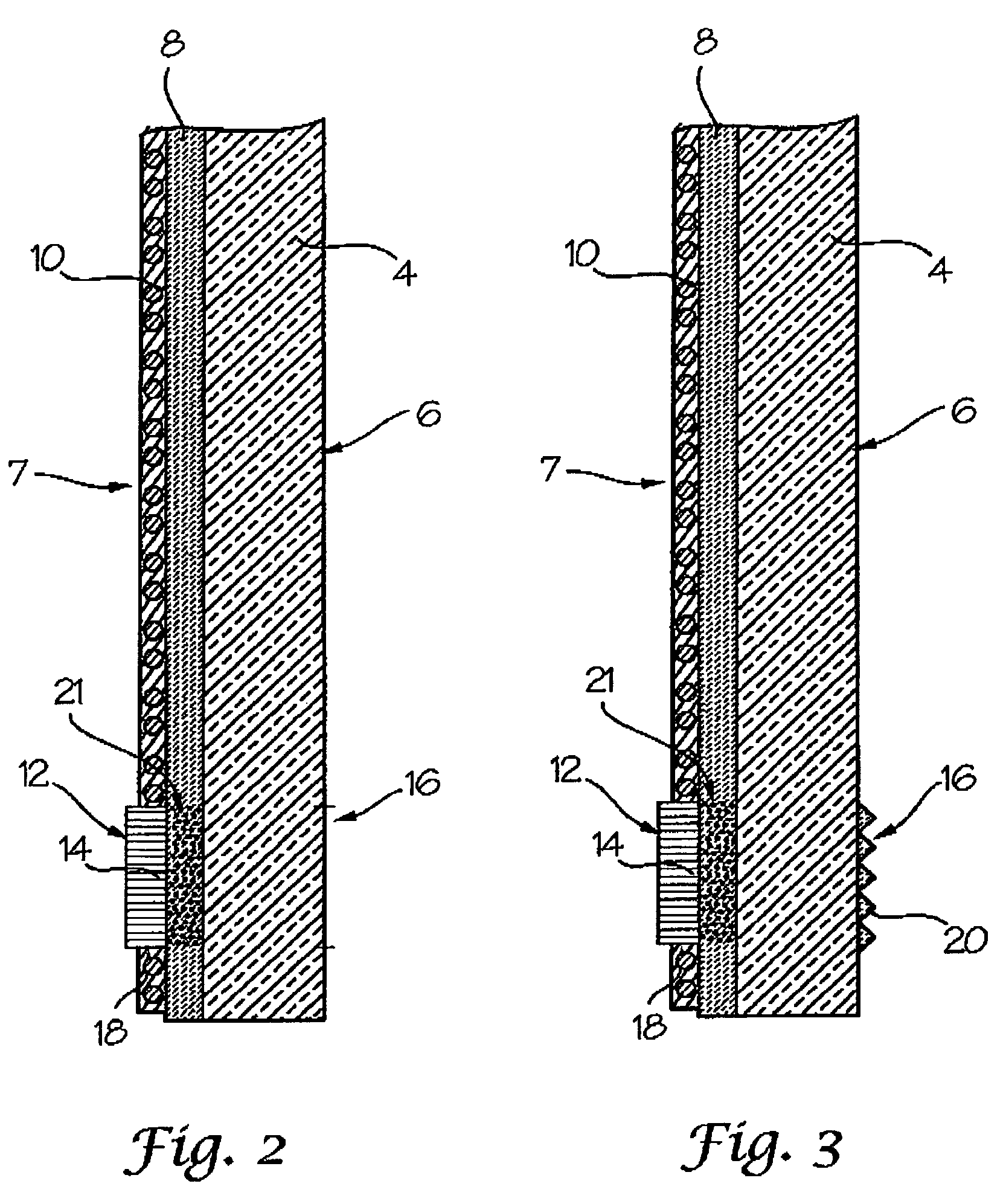
[0026]FIG. 2 shows the invention in a drawing similar to FIG. 1b which is different from the embodiment of FIG. 1 in that thermochromic heating indicator 12, depicted as thermochromic foil 14, is not located on front side 6 of mirror pane 4, but in a recess 18 in heating element 10 on reflecting surface 8. The surface on front side 6 of the mirror pane 4 acts as an indicator surface 16. To ensure that the change in color is visible from front side 6 of mirror pane 4 at indicator surface 16, reflecting surface 8 is removed or at least thinned in the area in which the thermochromic foil 14 is installed to allow the driver to view thermochromic heating indicator 12.

third embodiment

[0027]FIG. 3 shows the invention differentiated from the embodiment of FIG. 2 in that in addition an optical enhancing surface structure 20, preferably in the form of small prisms, is provided on front side 6 of mirror pane 4 in the area of indicator surface 16. The prisms 20 improve the visibility of thermochromic heating indicator 12. Alternatively a Fresnel lens structure may be provided to enhance visibility. This optical enhancing structure is possible in particular in optical heating indicators in the form of elements made of a thermochromic plastic, i.e. the optical enhancing structure is integrated into the thermochromic heating indicator 12.

[0028]FIG. 4 shows a fourth embodiment with the same basic structure as the second embodiment according to FIG. 2, but thermochromic foil 14 reacts by changing in transmissivity and not by changing color in response to temperature changes. When thermochromic materials are used that react to temperature changes with a change in their tran...

fifth embodiment

[0029]FIG. 5 shows the invention which differentiates itself from the embodiment of FIG. 4 in that the thermochromic foil 14 with changing transmissivity is located on front side 6 of mirror pane 4. Reflecting layer 8 is thinned or removed, indicated generally by reference number 21, beneath colored marker strip 22 so that the colored marking 22 mounted in recess 18 of heating element 10 becomes visible from the outside of mirror pane 4 as thermochromic foil 14 turns transparent.

[0030]FIGS. 6a and 6b show a sixth embodiment of the invention, where a strip 24 of thermochromic foil is placed in heat conducting contact with the back surface heating element 10 and extends between mirror housing 2 and mirror pane 4 outward to the area of the mirror housing that is visible with front side 6 of mirror pane 4. Portion 26 of thermochromic strip 24 is visible from front side 6 and acts as an indicator surface 16 for displaying operation of heating element 10. In the area in which thermochromi...


PUM


Abstract

A heatable external rearview mirror including a mirror housing for attachment to the vehicle and a mirror pane with a reflecting surface carried in the housing. A heating element is located adjacent the mirror pane for heating the pane to remove precipitation. A thermochromic heating indicator is provided in heat conducting contact with at least one of the heating element and the mirror pane that reacts to temperature changes for detecting heating of the mirror pane by the heating element and providing a visual indication of the operation of the heating element.

Description

BACKGROUND OF THE INVENTION[0001]1. Field of the Invention[0002]The present invention relates to automotive mirror assemblies, and more specifically, to a heatable external rearview mirror for motor vehicles that includes a thermochromic heating indicator for detecting heating of the mirror pane by a heating element and providing a visual indication of the operation of the heating element.[0003]2. Description of Related Art[0004]To design external rearview mirrors for motor vehicles so as to be heatable is known, so that condensate, frost, snow, ice, etc. may be removed by heating the mirror pane by means of a heating element in order to obtain an unobstructed field of vision to the rear through the mirror. Typically, the heating elements are made of surface heating elements extending essentially all across the expanse of the mirror pane at its back side with a mirror housing. It is also known to actuate the heating element in heatable rearview mirrors by means of a thermostatic swi...

Claims


Application Information

Patent Timeline
Patent Type & Authority Patents(United States)
IPC IPC(8): B60L1/02H05B3/00B60R1/06B60R1/12
CPCB60R1/0602B60R1/12
Inventor WITZKE, MICHAELSCHOLLER, JORGLANG, HEINRICH
Owner LANG MEKRA NORTH AMERICA LLC
Why Eureka
Try Eureka