
Monitoring propagation protection within a network

Inactive Publication Date: 2006-06-01
CYMTEC SYST
View PDF11 Cites 389 Cited by
  • Summary
  • Abstract
  • Description
  • Claims
  • Application Information

AI Technical Summary

Benefits of technology

[0007] In another aspect, there is a computerized method for propagation protection of email traffic within a network. The method includes repeatedly storing, by a network appliance, received portions of data associated with email in a buffer associated with an email message until an end of message indicator is received for the email message or a predefined number of bytes have been stored in the buffer before the end of message indicator is received, and preventing at least a final portion of data associated with the email message from being transmitted from the network appliance until a threat determination is made.
[0008] In another aspect, there is a network appliance for propagation protection of email traffic within a network. The network appliance includes a network interface card and a data analyzer module. The network interface card is configured to act as a bridge between a first portion of the network and a second portion of the network. The data analyzer module is configured to repeatedly store portions of data received from the first portion of the network and associated with email in a buffer associated with an email message until an end of message indicator is received for the email message or a predefined number of bytes have been stored in the buffer before the end of message indicator is received, and prevent at least a final portion of data associated with the email message from being transmitted to the second portion of the network until a threat determination is made.
[0016] The network appliance can determine whether a portion of data transmitted through the network appliance is associated with email. It can be determined whether the data is transmitted across a port associated with Simple Mail Transfer Protocol (SMTP). The storing can be performed only after a DATA command associated with the email message is received. The final portion of data can include a portion of data associated with the end of message indicator for the email message or reaching the predefined number of bytes for the email message. A number of buffers reserved for storage of received portions of data can be defined. Portions of data associated with another email message can be received. It can be determined that all of the defined number of buffers are currently associated with email messages different from the another email message. In such a case, transmission of the received portions of data associated with the another email message from the network appliance can be permanently prevented.
[0021] Implementations can realize one or more of the following advantages. The techniques enable a sensor device a unique ability to catch mass mailers that have their own email clients / servers. The techniques inhibit new (e.g., undiscovered) computer viruses from spreading through a corporate network based on the connection patterns they generate (e.g., statistical comparison). The techniques enable enforcement of corporate policy concerning what types of traffic are acceptable from their users and which could potentially pass virus traffic and / or harm the network. The threats are reported and organized for high visibility into traffic patterns, viewable by network security administrators. One implementation of the invention provides at least one of the above advantages.

Problems solved by technology

If the user inadvertently activates the threat before it is identified, the threat is able to infiltrate the corporate network, wreak havoc, and require an inordinate amount of unscheduled resources of a corporation's information technology department to track the source of the threat, isolate the threat, and eliminate it and all of its spawned malicious processes from the network.

Method used


Image

  • Monitoring propagation protection within a network
  • Monitoring propagation protection within a network
  • Monitoring propagation protection within a network

Examples


Embodiment Construction

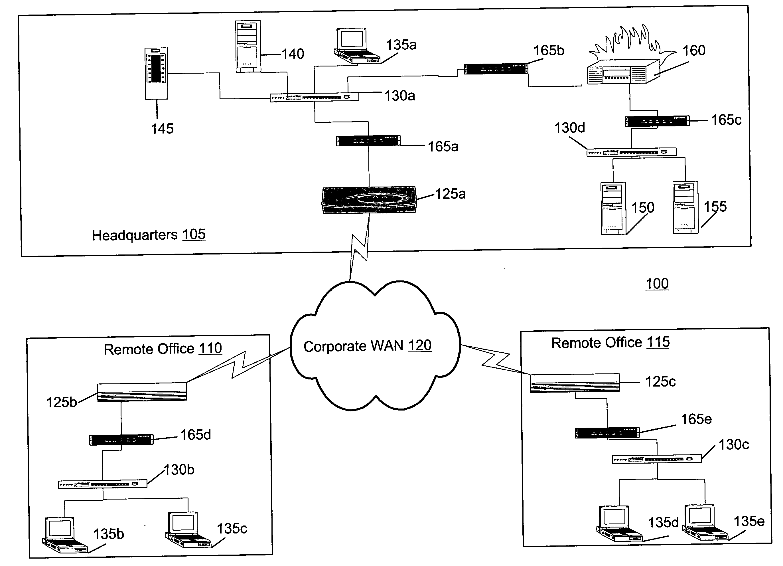
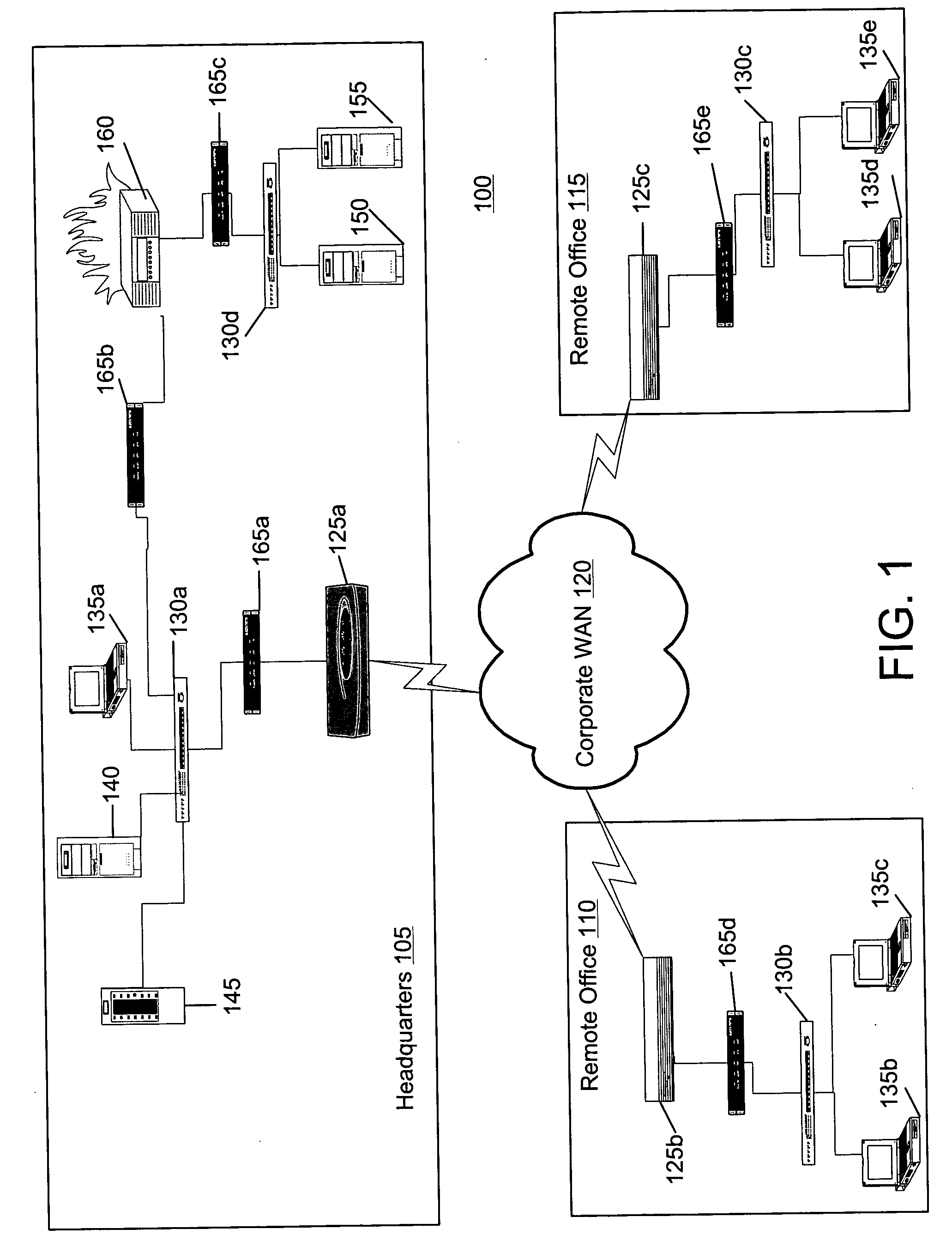
[0033]FIG. 1 illustrates a computer system 100 used for propagation protection within a network. The system 100 represents an exemplary system that might be used by a corporation having remote offices. The system 100 includes a first portion 105 that is located at the headquarters of the corporation, a second portion 110 located at a first remote office, and a third portion 115 located at a second remote office. The portions 105, 110, and 115 are in communication with each other via a corporate wide area network (WAN) 120. The WAN 120 can include a private network maintained by the corporation, a virtual private network implemented on a public WAN, such as the Internet, a packet-based network, a circuit-based network (e.g., public switched telephone network (PSTN)) and / or the like. The portions 105, 110, and 115 include routers 125a, 125b, and 125c, respectively, generally referred to as a router 125, that route data to each other and to respective local area network (LAN) switches ...


PUM


Abstract

Described are methods and apparatus, including computer program products, for propagation protection within a network. A management station receives event messages from a plurality of transparent network appliances, each of the event messages comprising a threat indication generated in response to a detected threat in data being transmitted through the respective transparent network appliance.

Description

RELATED APPLICATIONS [0001] This application claims priority under 35 U.S.C. 119 to U.S. provisional patent application No. 60 / 631,764 filed on Nov. 30, 2004 and hereby incorporated by reference. This application is related to application S / N TBA, attorney docket number CMT-001A, entitled “Propagation Protection Within A Network”, filed on the same day and hereby incorporated by reference. This application also is related to application S / N TBA, attorney docket number CMT-001B, entitled “Propagation Protection Of Email Traffic Within A Network”, filed on the same day and hereby incorporated by reference.FIELD OF THE INVENTION [0002] The present invention relates to computer-based methods and apparatuses, including computer program products, for propagation protection within a network. BACKGROUND [0003] Typical protection of a network focuses on keeping a threat (e.g., virus, worm, etc.) from entering the network. Firewalls are used to separate a portion of the network that interface...

Claims


Application Information

Patent Timeline
IPC IPC(8): G06F12/14
CPCG06F21/552G06F2221/2101H04L12/585H04L43/045H04L51/12H04L63/0227H04L63/14H04L63/1441H04L63/20H04L51/212
Inventor MESTER, MICHAEL L.GUNSALUS, BRADLEY W.
Owner CYMTEC SYST
Learn More