

Automatic light dimmer for electronic and magnetic ballasts (fluorescent or HID)
a technology of electronic and magnetic ballasts and automatic light dimmer, which is applied in the direction of light sources, lighting devices, instruments, etc., can solve the problems of system interaction with internal elements of electronic ballasts, sudden lighting changes, and cables to be added to lighting circuits, etc., to achieve convenient and competitive prices, high power factor of electronic ballasts, and energy saving
- Summary
- Abstract
- Description
- Claims
- Application Information
AI Technical Summary
Benefits of technology
Problems solved by technology
Method used
Image

Examples
example 1
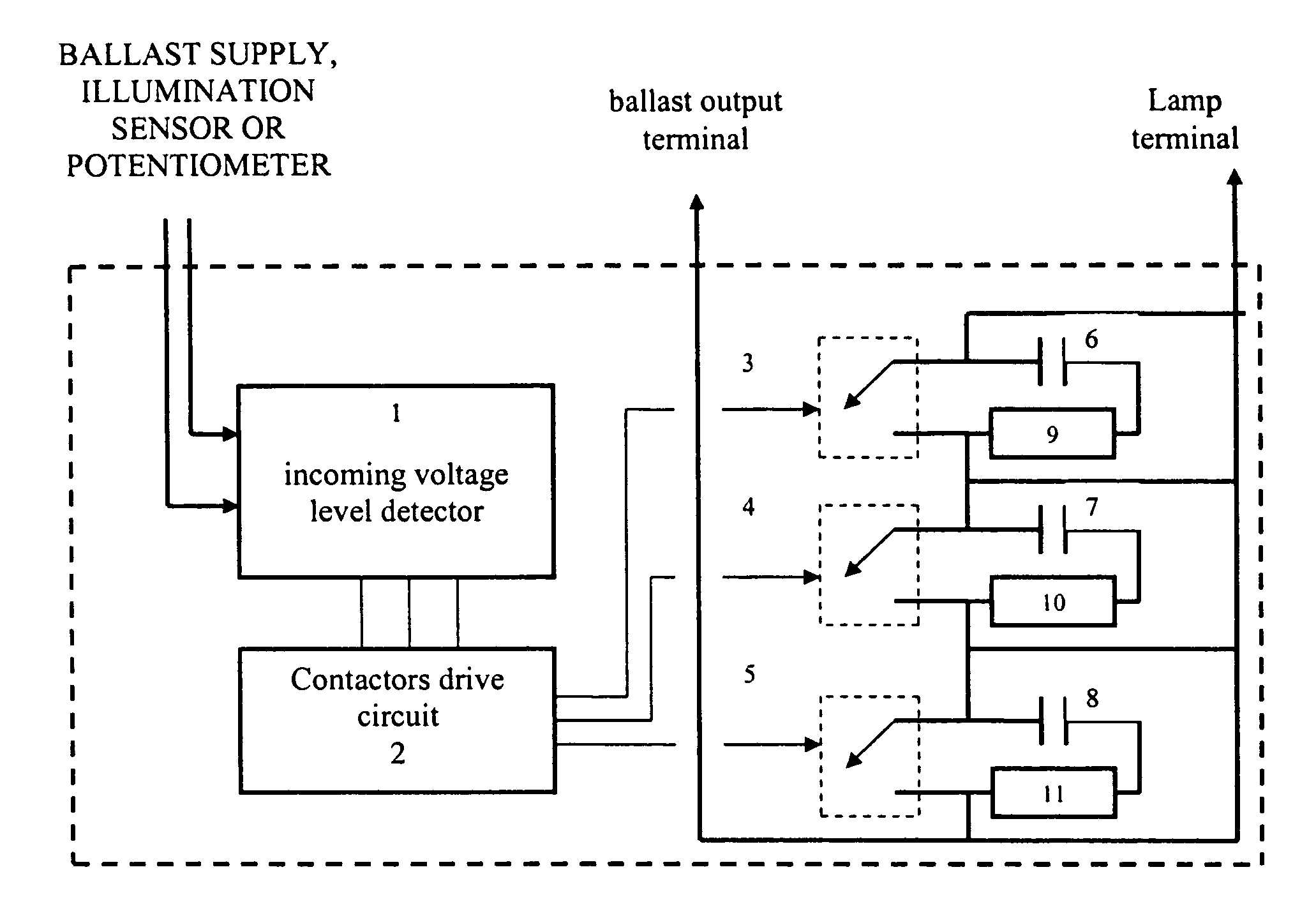
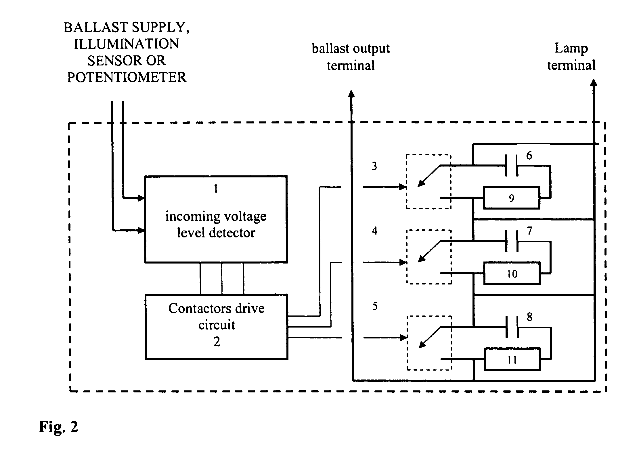
[0047]
A. Condition to obtain a normal illumination where input voltage is from a ballast supply.
input voltage>selected voltage 1
The maximum input voltage is in function off the maximum operate ballast_voltage.
B. Condition to obtain an illumination with a minimum reduction (first reduction step) where input voltage is from a ballast supply.
input voltage
input voltage>selected voltage 2
Both conditions must be met.
C. Condition to obtain an illumination with a half reduction (second reduction step) where input voltage is from a ballast supply.
input voltage
input voltage>selected voltage 3
Both conditions must be met.
D. Condition to obtain an illumination with a maximum reduction (third reduction step) where input voltage is from a ballast supply.
input voltage
The minimum input voltage is in function off the minimum operate ballast voltage.
[0048] Alternatively, the input voltage can be...
example 2
[0050]
Input Voltage=Voltage Illumination Sensor
A. Condition to obtain a normal illumination where the input voltage is from an illumination sensor.
input voltage
B. Condition to obtain an illumination with a minimum reduction (first reduction step) where the input voltage is from an illumination sensor.
input voltage>selected voltage 3
input voltage
Both conditions must be met.
C. Condition to obtain an illumination with a half reduction (second reduction step) where the input voltage is from an illumination sensor.
input voltage>selected voltage 2
input voltage
Both conditions must be met.
D. Condition to obtain an illumination with a maximum reduction (third reduction step) where the input voltage is from an illumination sensor.
input voltage>selected voltage 1
The following formulas can be used to select the values of R1 and R2 resistances as well as the reference voltage and selected voltage for the illumination co...
PUM
 Abstract
Description
Claims
Application Information