
Thermal developing apparatus

Inactive Publication Date: 2006-06-08
FUJIFILM HLDG CORP +1
View PDF2 Cites 0 Cited by
  • Summary
  • Abstract
  • Description
  • Claims
  • Application Information

AI Technical Summary

Benefits of technology

[0010] The present invention has been made in view of the above circumstances, and it is an object of the present invention to provide a thermal developing apparatus capable of preventing control of a heating temperature during thermal development from becoming difficult, by eliminating unevenness in a temperature distribution of a heating unit.
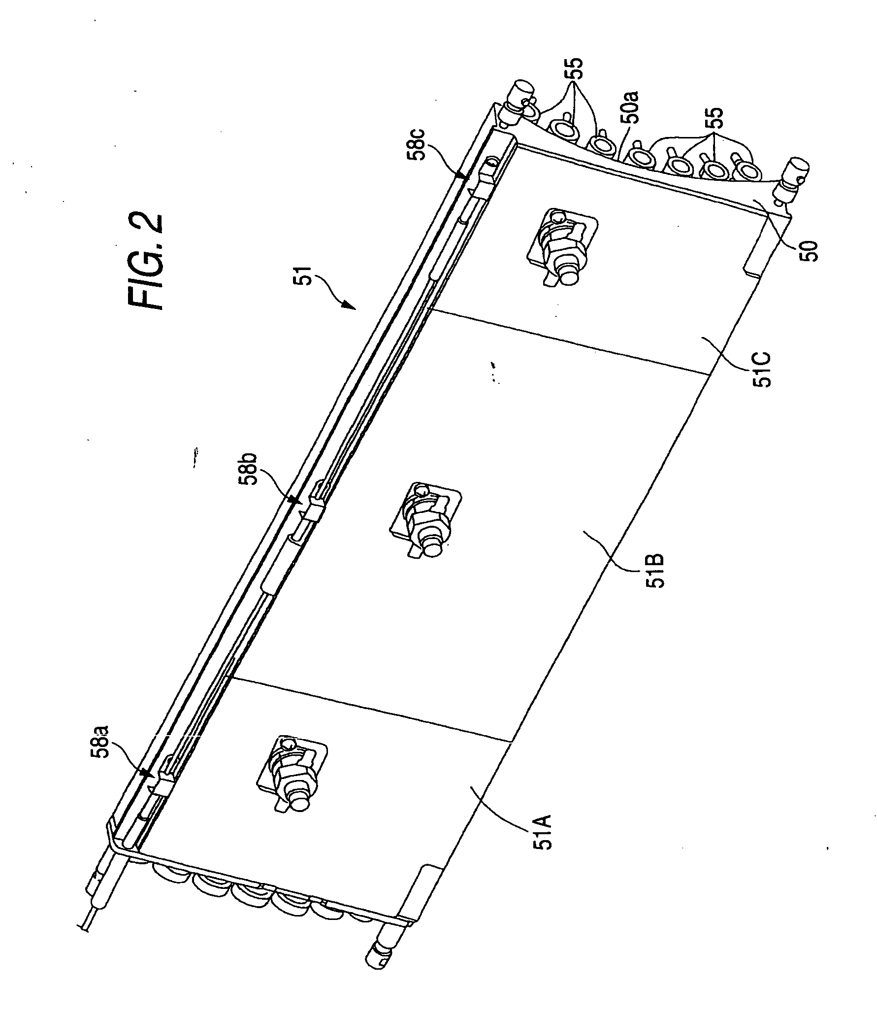
[0012] The thermal developing apparatus according to the present invention is constructed to have the temperature measuring portions and to measure the center portion of the temperature distribution in each of a plurality of heating portions by the temperature measuring portions respectively. Thus, in contrast to the case where the center position in the heating portions, which are aligned as the heating unit in the direction that intersects orthogonally with the carrying direction of the thermally developing recording material, in the orthogonal direction is measured, the temperature difference between the measuring position and surrounding positions can be reduced by measuring the center portion of the temperature distribution in respective heating portions, as set forth in this application. Therefore, it can be prevented that control of adjusting the temperature of the heating portions in response to the temperature measured by the temperature measuring portions becomes complicated at the time of thermal development. Also, the heating portions in the heating unit can be controlled more precisely. In this manner, it can be prevented that unevenness of the density of the recording material F that was subjected to the thermal development is generated due to generation of unevenness of the heating temperature of the heat plate 51.

Problems solved by technology

Thus, it was extremely difficult to control the heating portions 2, 3, 4 respectively such that the heat plate 1 should be kept at a substantially constant temperature as a whole at the time of thermal development.
As a result, in some cases the unevenness of the heating temperature was generated in the heat plate 1.

Method used


Image

  • Thermal developing apparatus
  • Thermal developing apparatus
  • Thermal developing apparatus

Examples


Embodiment Construction

[0022] An embodiment of the present invention will be explained in detail with reference to the drawings hereinafter.

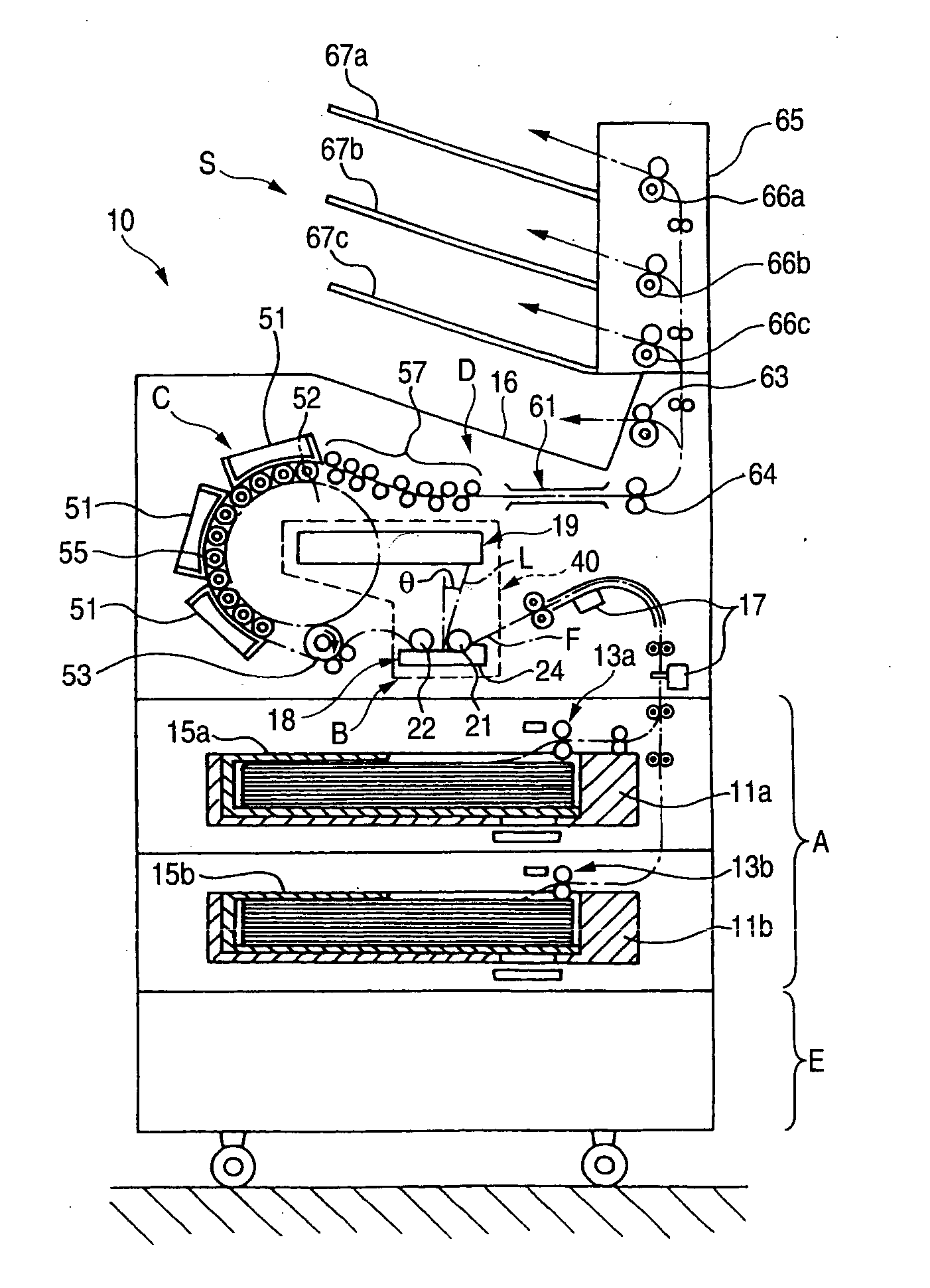
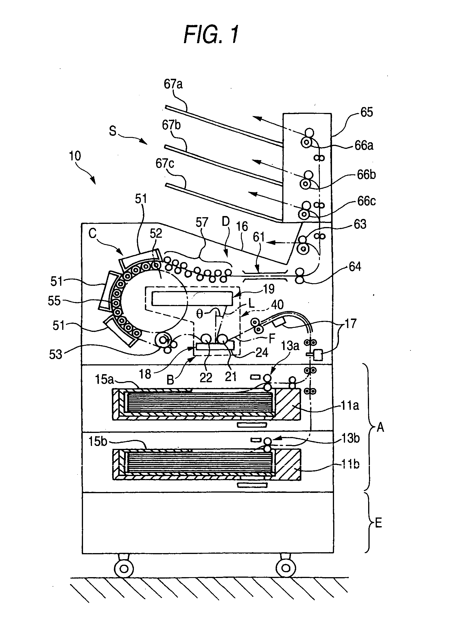
[0023]FIG. 1 is a view showing an embodiment of a thermal developing apparatus according to the present invention.

[0024] As shown in FIG. 1, a thermal developing apparatus 10 of the present embodiment has such a configuration that a sheet-like thermally developing recording material (referred to as a “recording material” hereinafter) F that does not need the wet developing process is employed as the image recording material, then a latent image is formed by irradiating a laser light L that is modulated based on an image signal input into the recording material F, and then a visible image is obtained on a surface of the recording material by thermally developing the recording material F. In this case, the present invention is not limited to such configuration. The present invention can be applied to such a configuration that the image is formed by exposing previously...


PUM


Abstract

A thermal developing apparatus for thermally developing a latent image formed on a thermal developing recording material by a thermal developing portion, the apparatus comprising: a heating unit that heats the thermal developing recording material carried to the thermal developing portion, the heating unit comprising a plurality of heating portions that are aligned in a direction that intersects orthogonally with a carrying direction of the thermal developing recording material; and a plurality of temperature measuring portions that measure temperatures of the plurality of heating portions respectively, each of said plurality of temperature measuring portions being arranged to measure a center portion of a temperature distribution in each of said plurality of heating portions.

Description

BACKGROUND OF THE INVENTION [0001] 1. Field of the Invention [0002] The present invention relates to a thermal developing apparatus for thermally developing a latent image, which is formed on an image forming layer of a thermally developing recording material, by heating the thermally developing recording material. [0003] 2. Description of the Related Art [0004] In recent years, the thermal developing apparatus and the thermal developing / recording apparatus that never applies the wet process and uses the dry system have been proposed. In such thermal developing apparatus and such thermal developing / recording apparatus, the photosensitive and / or thermal recording material (photosensitive / thermal recording material) or the film-like recording material containing the thermally developing photosensitive material (referred to as a “thermally developing recording material” hereinafter) is used as the recording medium. Also, in the thermal developing apparatus and the thermal developing / re...

Claims


Application Information

Patent Timeline
IPC IPC(8): B41J2/36
CPCB41J2/36
Inventor KAMA, TAKESHI
Owner FUJIFILM HLDG CORP
Learn More