
Apparatus for creating effectively transparent A-pillars on vehicle

a technology of transparent a-pillars and apparatuses, which is applied in the direction of color television details, closed-circuit television systems, television systems, etc., can solve the problems of structural safety and cost that are difficult to overcome, and the option of a-pillar materials is very limited, so as to improve the safety of vehicles.

Inactive Publication Date: 2006-06-08
ARBL
View PDF4 Cites 47 Cited by
  • Summary
  • Abstract
  • Description
  • Claims
  • Application Information

AI Technical Summary

Benefits of technology

[0005] The primary object of the present invention is to provide an apparatus to enhance vehicle safety by giving drivers a visual image originally blocked by A-pillars of the vehicle when driving.
[0008] The invention further has an image processor. A full scope display panel is installed on the inner side of the A-pillar of the vehicle, and a video camera array is installed on the outer side of the A-pillar to capture images of different angles. The image signals are transferred to the image processor and are integrated and displayed on the full scope display panel so that the driver can get a visual image equivalent of a transparent A-pillar to enhance driving safety.

Problems solved by technology

Abundance of evidence shows that many car driving accidents were in fact caused by the blinding effect of these opaque A-pillars on two sides of the cars' windshields.
Especially while the vehicle is making a turn, if a motorcycle nearby is also making a similar move, with an angular frequency close to that of the vehicle though at a lower speed, the car driver's vision of the motorcycle may be temporarily blocked by one of his own A-pillars and an accident will likely happen within a fairly short period of time.
However, there are other structural concerns other than the mere fact that the A-pillars are supposed to support the top of vehicle.
Hence, the option for A-pillar materials is very limited.
To fabricate A-pillars using transparent materials faces many problems arising from the sides of structural technology, structural safety and cost that are difficult to overcome.
While such an approach can reduce the vision hindrance of the drivers, its unusual design and manufacturing to meet the structural strength requirements have obviously raised the vehicle's cost considerably.

Method used


Image

  • Apparatus for creating effectively transparent A-pillars on vehicle
  • Apparatus for creating effectively transparent A-pillars on vehicle
  • Apparatus for creating effectively transparent A-pillars on vehicle

Examples


Embodiment Construction

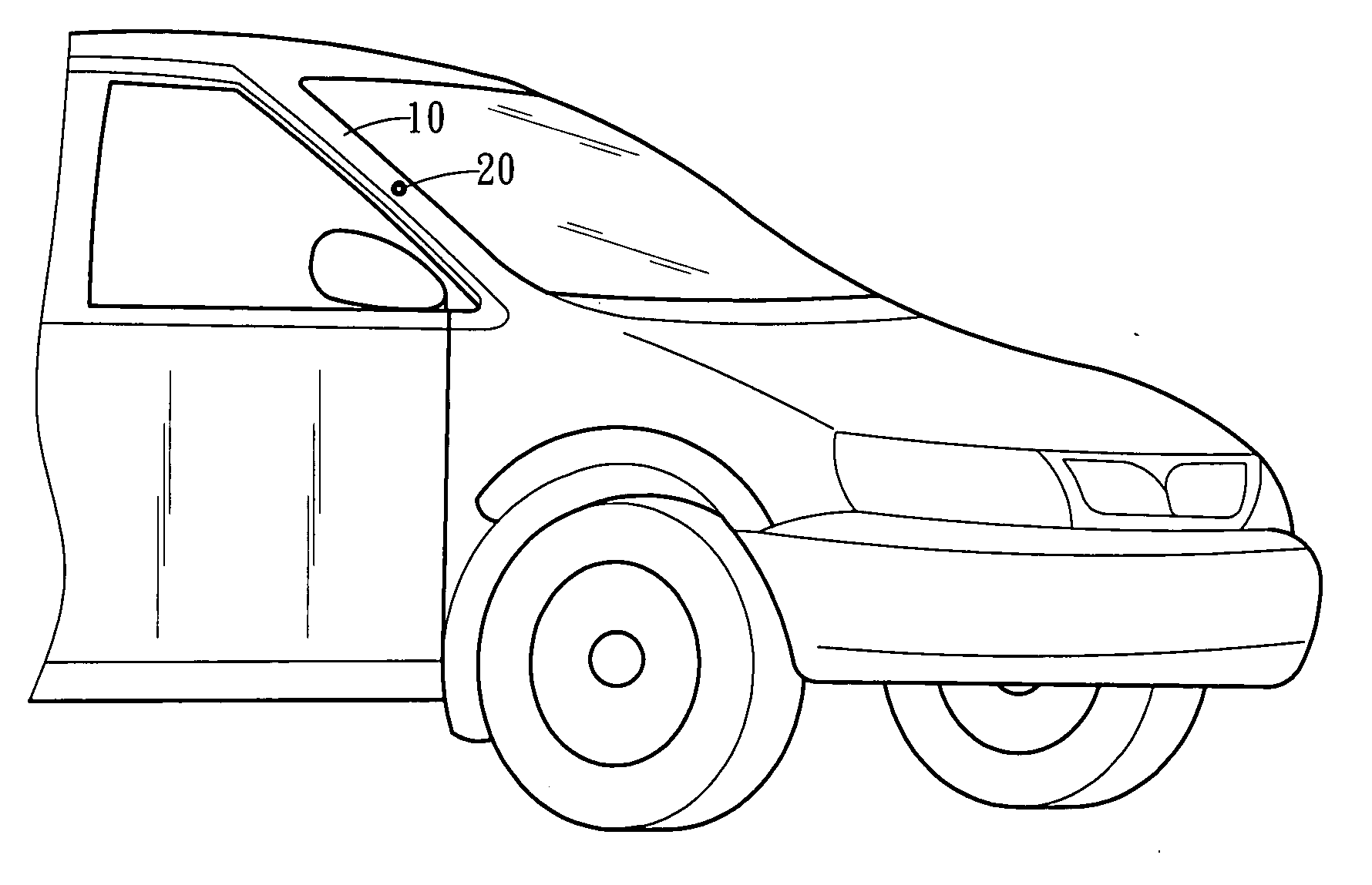
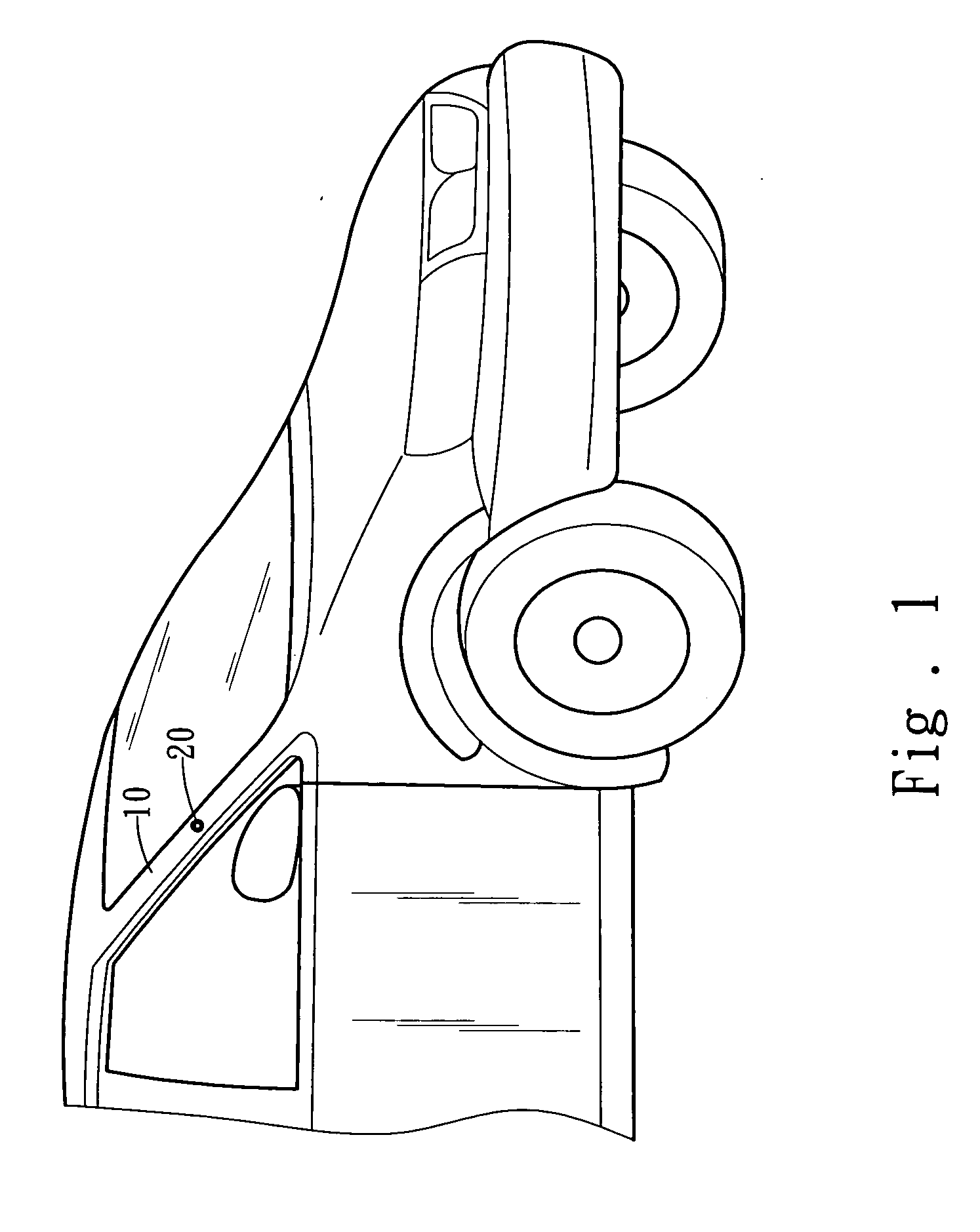
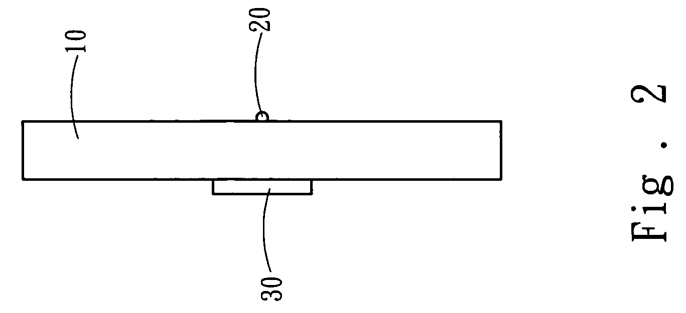
[0015] Please refer to FIGS. 1 and 2 for the apparatus of the present invention that enables a vehicle A-pillar 10 to have a transparent-like effect. The vehicle A-pillar 10 has a video camera 20 installed on an outer side and a display panel 30 installed on an inner side. The display panel 30 can receive image signals from the video camera 20 and display the captured images.

[0016] The display panel 30 may be selected from liquid crystal display (LCD), light emitting diode (LED) or organic LED (OLED). The video camera 20 is a pin-hole video camera which captures images and sends image signals via a wireless or wired transmission method to the display panel 30. The captured images can be instantly displayed on the display panel 30. Thereby the driver can see the images blocked by the A-pillar 10 to enhance driving safety.

[0017] Refer to FIGS. 3, 4 and 5 for a second embodiment of the present invention. It further has an image processor 40. The vehicle A-pillar 10 has a full scope d...


PUM


Abstract

An apparatus to enhance driving safety for vehicles especially in the dynamic conditions at turning includes a display panel installed on an inner side of the vehicle A-pillar and a video camera installed on an outer side of the A-pillar. Vision outside the A-pillar can be dynamically captured by the video camera and displayed on the display panel. Hence the visual scope of the driver increases. A video camera array can be provided to capture the images of different angles. And an image processor is provided to process the images and display a full scope image on a full scope display panel on the inner side of the A-pillar. Thereby the driver can get a visual image equivalent to a transparent A-pillar to enhance driving safety.

Description

FIELD OF THE INVENTION [0001] The present invention relates to a safety apparatus for vehicle and particularly to an apparatus to produce a transparent-like effect on A-pillars of vehicle to facilitate drivers with unhindered visual sight at side angles for enhanced driving safety. BACKGROUND OF THE INVENTION [0002] A car's A-pillars are formed as part of the vehicle body and are normally opaque. Abundance of evidence shows that many car driving accidents were in fact caused by the blinding effect of these opaque A-pillars on two sides of the cars' windshields. Especially while the vehicle is making a turn, if a motorcycle nearby is also making a similar move, with an angular frequency close to that of the vehicle though at a lower speed, the car driver's vision of the motorcycle may be temporarily blocked by one of his own A-pillars and an accident will likely happen within a fairly short period of time. Thus, very often, it is only after an impact has occurred then the car driver ...

Claims


Application Information

Patent Timeline
IPC IPC(8): H04N7/18H04N9/47
CPCB60R1/00B60R2300/105B60R2300/202B60R2300/30B60R2300/406B60R2300/802H04N7/183B60R1/25
Inventor LIAO, CHUNGPIN
Owner ARBL
Learn More