Modular arrangement of components of electrical equipment enclosure

a technology of modular arrangement and components, applied in the direction of switchgear arrangement, electrical equipment, arrangement with metal casings, etc., can solve the problems of not being able to be removed without the use of tools, requiring special tooling, and additional time with the overall system down

Inactive Publication Date: 2006-06-08
SIEMENS CORP
View PDF3 Cites 24 Cited by
  • Summary
  • Abstract
  • Description
  • Claims
  • Application Information

AI Technical Summary

Benefits of technology

[0008] There is also provided a method for assembling and maintaining a primary disconnect in a switchgear enclosure having a circuit breaker mounting base and one of a run-back bus bar and run-in bus bar mounted through an orifice in the mounting base. The method comprises the steps of providing a-mounting base with alignment notches. Providing a bridge having at least one alignment tab configured to engage the alignment notch and mounting the bridge in the alignment notch. Providing a primary disconnect bus. Positioning the primary disconnect bus against the alignment bridge to align the primary disconnect bus front to back and adjacent to the run-back bus bar or run-in bus bar to align the primary disconnect bus side-to-side. Connecting the primary disconnect bus to the run-back bus bar or run-in bus bar with a fastener to align the primary disconnect bus top to bottom. The assembly and maintenance of the primary disconnect is performed at the front of the switchgear enclosure. Another embodiment includes performing the same method for each run-back bus bar or run-in bus bar of each phase in the mounting phase.
[0009] There is also provided a method for assembling and maintaining a primary disconnect and a switchgear enclosure having a circuit breaker mounting base and one of a run-back bus bar and run-in bus bar mounted through an orifice in the mounting base. The method comprises the steps of providing alignment ribs in the mounting base. Providing a primary disconnect bus, with the primary disconnect bus having two branches and defining rib notches. Positioning the primary disconnect bus and the mounting-base to align the primary disconnect bus front to back and adjacent to the run-back bus bars or run-in bus bars to align the primary disconnect bus side-to-side. Engaging the alignment ribs with the rib notches in the primary disconnect bus. Connecting the primary disconnect bus to the run-back bus bar or run-in bus bar with a fastener to align the primary disconnect bus top to bottom. The assembly and maintenance of the primary disconnect bus is performed at the front of the switchgear enclosure. Another embodiment of the method includes coupling each run-back bus bar or run-in bus bar of each phase in the mounting base.

Problems solved by technology

In a stationary construction, the circuit breaker is bolted to the structure both mechanically and electrically and is not removable without the use of tools.
Known primary disconnects for electrical equipment, particularly circuit breakers typically are not replaceable from inside the breaker compartment.
Access to change out or repair primary disconnects in prior art patents require access from the rear of the equipment and may require extensive disassembly of equipment and components within the enclosure.
Known methods of alignment of primary disconnects include the use of a stab positioning system, however, such system typically requires rear access to secure the disconnect with a bolt.
Such procedures require special tooling and additional time with the overall system down.

Method used


Image

  • Modular arrangement of components of electrical equipment enclosure
  • Modular arrangement of components of electrical equipment enclosure
  • Modular arrangement of components of electrical equipment enclosure

Examples


Embodiment Construction

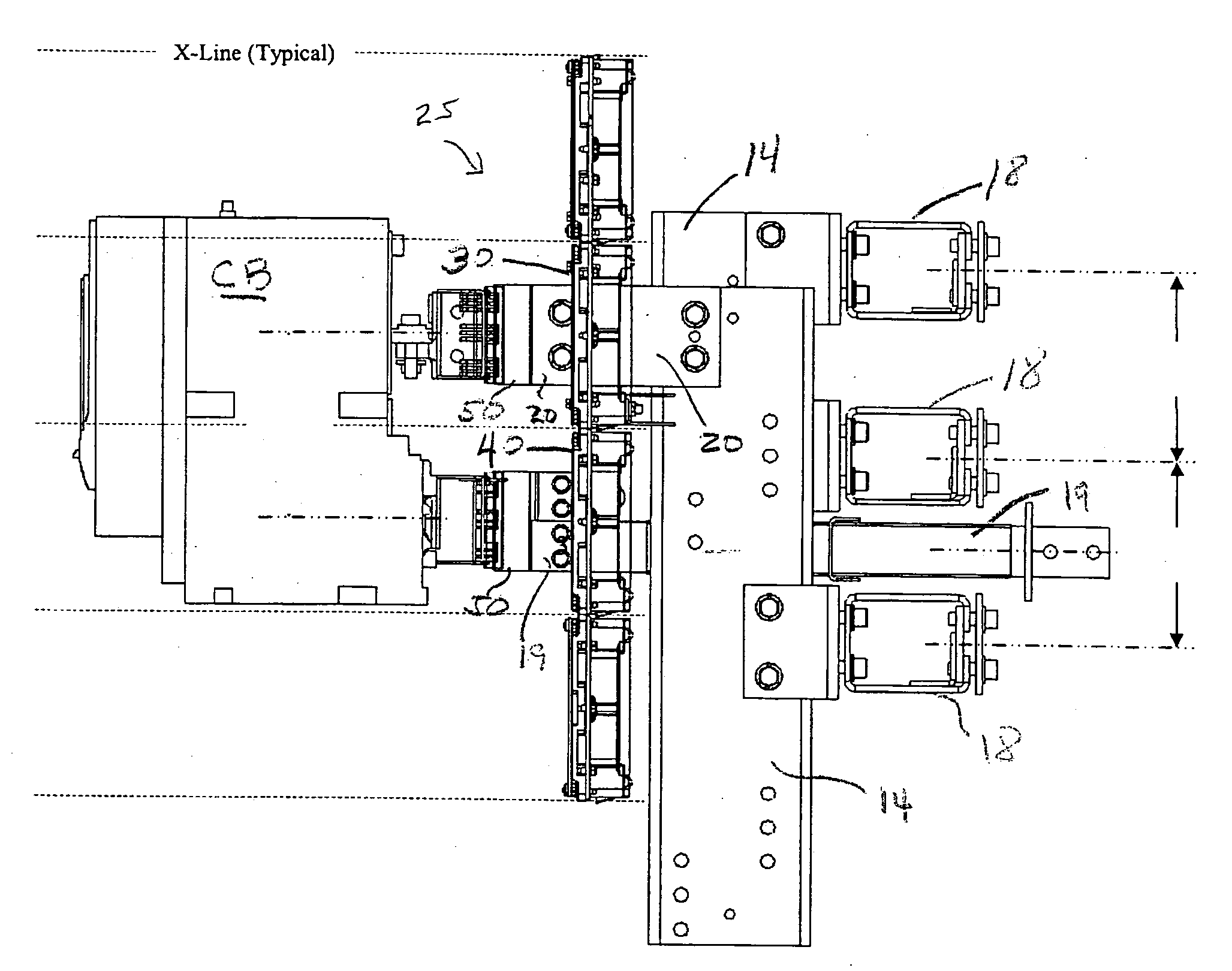
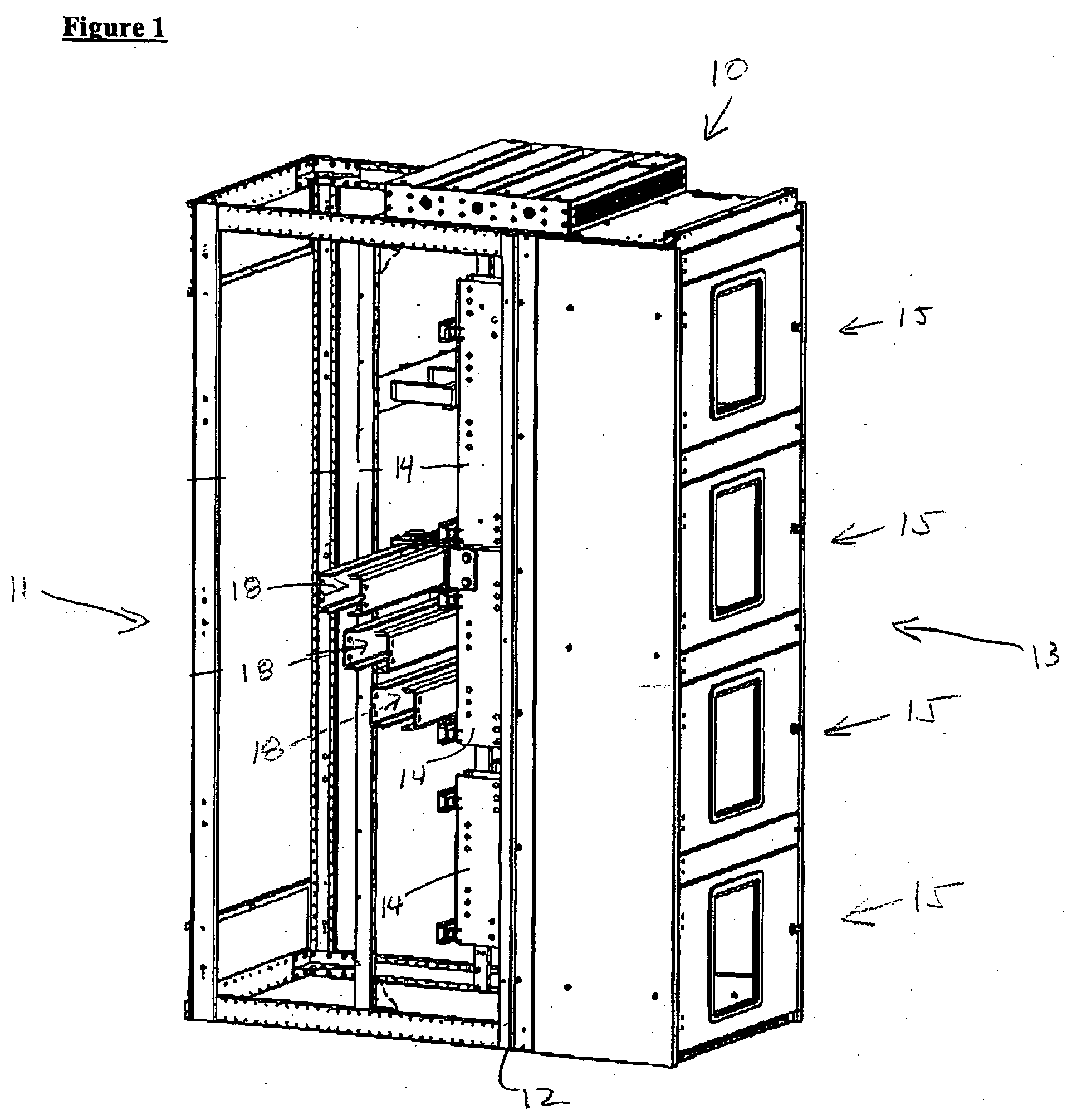
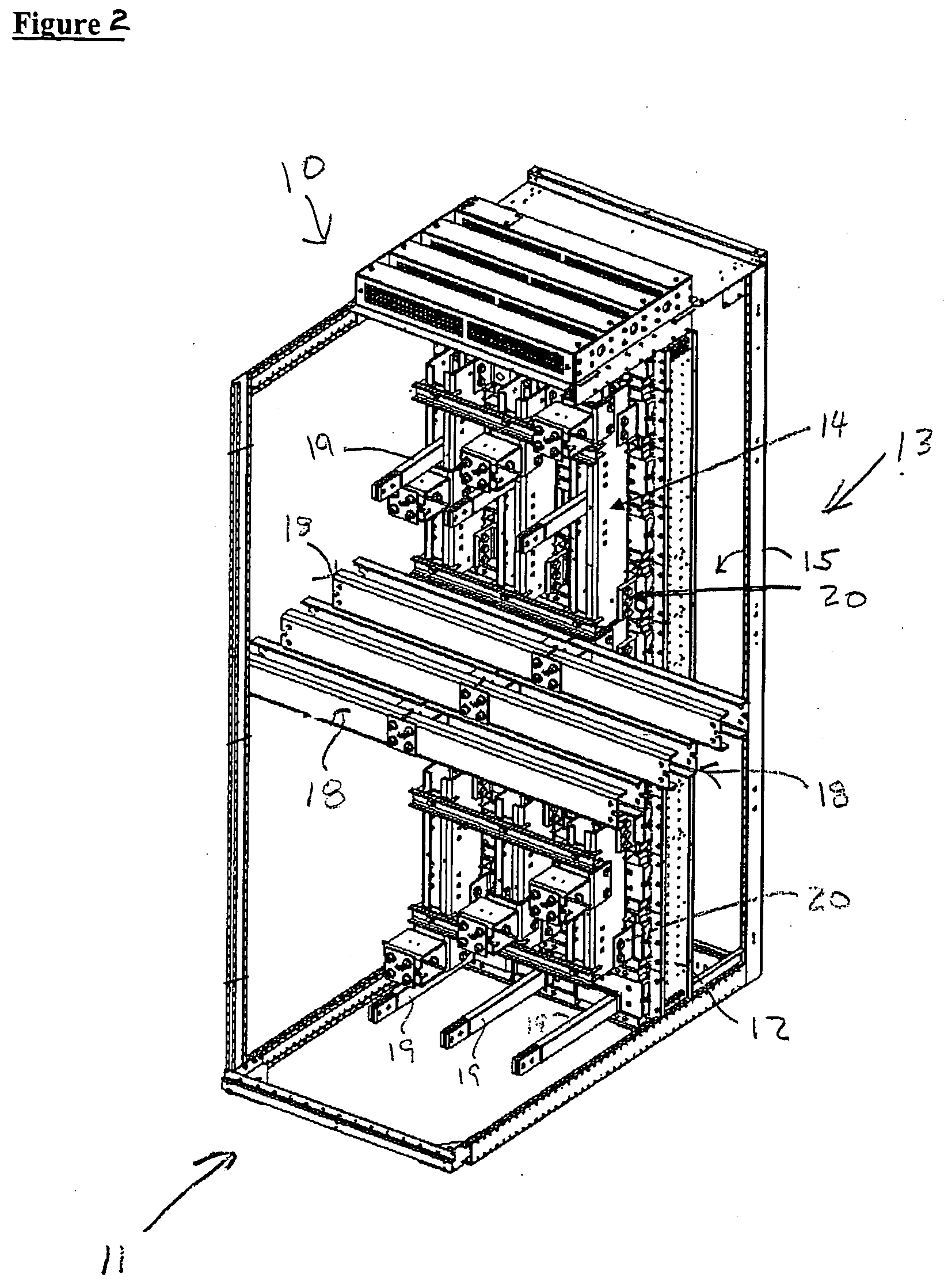
[0021] Before describing the exemplary embodiments of an arrangement of components 25 in an electrical equipment enclosure 10, for example, a switchgear enclosure, having multiple-phase (A, B, C) electrical power run-in bus bars 20 and run-back bus bars 19, several comments are appropriate. Switchgear assemblies and panel board assemblies typically include vertical (section) bus bars to distribute electrical power within the enclosure. In a short circuit condition, extreme magnetic forces are created in the bus bars as a result of short circuit currents up to and including 200,000 amps symmetrical RMS flowing through each bus bar. For a low voltage switchgear and switch boards operating at voltages up to 600 volts and continuous currents that can exceed 5,000 amps. In a three phase power system (typically) as a short circuit current flows through such bus bars, magnetic forces between adjacent bus bars tend to move such bus bars laterally (perpendicular) to the current flow. The cir...


PUM


Abstract

A method and an arrangement of components in a switchgear enclosure having multi-phase electrical power run-in and run-back bus bars. The circuit breaker is also provided in the enclosure. The arrangement of components is configured to provide interchangeable modularity of components within the enclosure. The arrangement of components includes a run-in mounting base including a primary disconnect member for each electrical phase. A run-back mounting base, including a primary disconnect member for each electrical phase is also included. The run-in mounting base and the run-back mounting base are configured to interchange the line and load side of the circuit breaker. Another embodiment of the arrangement includes a bridge coupled to one of the run-in mounting base and run-back mounting base, with the bridge configured to position each primary disconnect member for alignment with the circuit breaker. 136

Description

FIELD [0001] The present invention generally relates to the field of electrical switchboards and panel boards, and more particularly to a modular arrangement of components of an electrical equipment enclosure having multi-phase electrical power bus bars. BACKGROUND [0002] Switchgear assemblies and switchboards and panel boards are general terms which cover metal enclosures, housing switching and interrupting devices such as fuses and circuit breakers, along with associated control, instrumentation and metering devices. Such assemblies typically include associated bus bars, interconnections and supporting structures used for the distribution of electrical power. Low voltage switchgear and switchboards operate at voltages of up to 600 volts and with continuous currents up to 5000 amps or higher. Such devices are also designed to withstand short circuit currents ranging up to 200,000 amps (3 phase RMS symmetrical). [0003] Typical switchgear equipment is composed of a lineup of several ...

Claims


Application Information

Patent Timeline
Patent Type & Authority Applications(United States)
IPC IPC(8): H02B13/02
CPCH02B1/21
Inventor WIANT, JASON P.JOSTEN, HARRY W.MEYER, ROBERT D.WEDEMEYER, RUSSELL J.
Owner SIEMENS CORP
Why Eureka
Try Eureka