Packet forwarding apparatus and communication network suitable for wide area ethernet service

a technology of packet forwarding and communication network, applied in electrical equipment, data switching network, digital transmission, etc., can solve the problems of large equipment investment, increased cost, server cracking, etc., and achieve the effect of reducing the required cos

Inactive Publication Date: 2006-06-08
HITACHI LTD
View PDF17 Cites 57 Cited by
  • Summary
  • Abstract
  • Description
  • Claims
  • Application Information

AI Technical Summary

Benefits of technology

[0025] It is therefore an object of the present invention to provide a communication network and a packet forwarding apparatus by which the access service provider can realize offering wide area Ethernet services to Internet access subscriber users at low cost.
[0026] It is another object of the present invention to provide a communication network and a packet forwarding apparatus allowing for offering wide area Ethernet service to subscriber users, while ensuring access network security.
[0036] A packet to be communicated over a wide area Ethernet network is encapsulated in Bridge over PPP form prescribed by RFC 3518 at each gateway and transmitted to the peer LAC via a PPPoE session. Since the LAC ignores protocols higher than PPP, it eliminates the PPPOE header from the received packet, encapsulates the PPP packet in L2TP form, and forward the L2TP packet to the L2TP packet forwarding apparatus through the L2TP session having been set up beforehand. The L2TP packet forwarding apparatus retrieves a VPN-ID based on the tunnel ID / session ID pair of the received packet, and determines whether another L2TP session associated with the VPN-ID exists. If another L2TP session associated with the same VPN-ID exists, the L2TP packet forwarding apparatus forwards the received packet to another L2TP session, whereby user-to-user connectivity on virtual Ethernet can be ensured.
[0037] According to the present invention, only by adding the L2TP packet forwarding apparatus to the Internet access network formed by an IP network and making some change in parameter setting of gateways connected to the LACs, the access service provider can provide virtual wide area Ethernet services to existing subscriber users. According to the present invention, a wide area Ethernet network for connecting many communication bases can be formed by utilizing commonly used IP network communications technology and commonly used tunneling protocols, and it is able to reduce required cost greatly as compared with the first method using switching hubs and optical interfaces and the second method using EoMPLS discussed as prior art.

Problems solved by technology

However, the above prior art wide area Ethernet implementations have the following problems.
For instance, if the first method using switching hubs and optical interfaces is applied in an extensive communication area, the number of switching hubs to be deployed increases because of physical limitation of optical interfaces, which results in increase in the cost.
To equip the communication nodes on all paths through which EoMPLS packets pass with the label switching function, a large sum of equipment investment is needed.
In the case of the third method that connects virtual tunnels set up on the IP network to a virtual switching hub server, because a service for accessing the server based on an IP address must be offered to users, there is a possibility that the server is cracked and this poses a problem in security.
Furthermore, given that the provider of access service oriented to home users provides user-to-user connection services by wide area Ethernet to subscriber users, according to one of the above prior art methods, following problems would arise.

Method used


Image

  • Packet forwarding apparatus and communication network suitable for wide area ethernet service
  • Packet forwarding apparatus and communication network suitable for wide area ethernet service
  • Packet forwarding apparatus and communication network suitable for wide area ethernet service

Examples


first embodiment

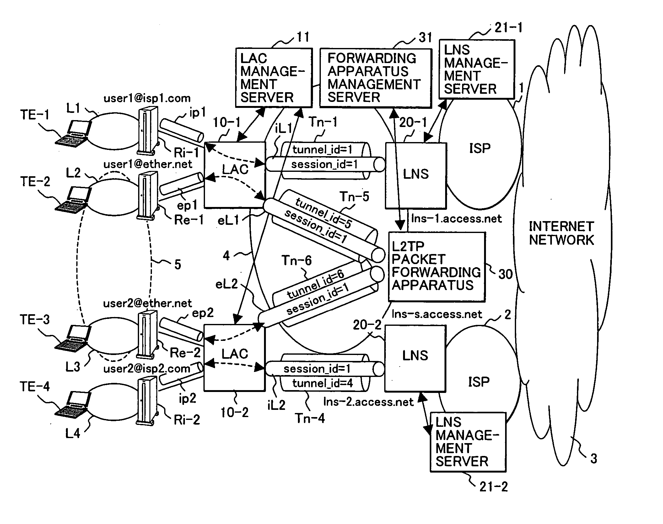
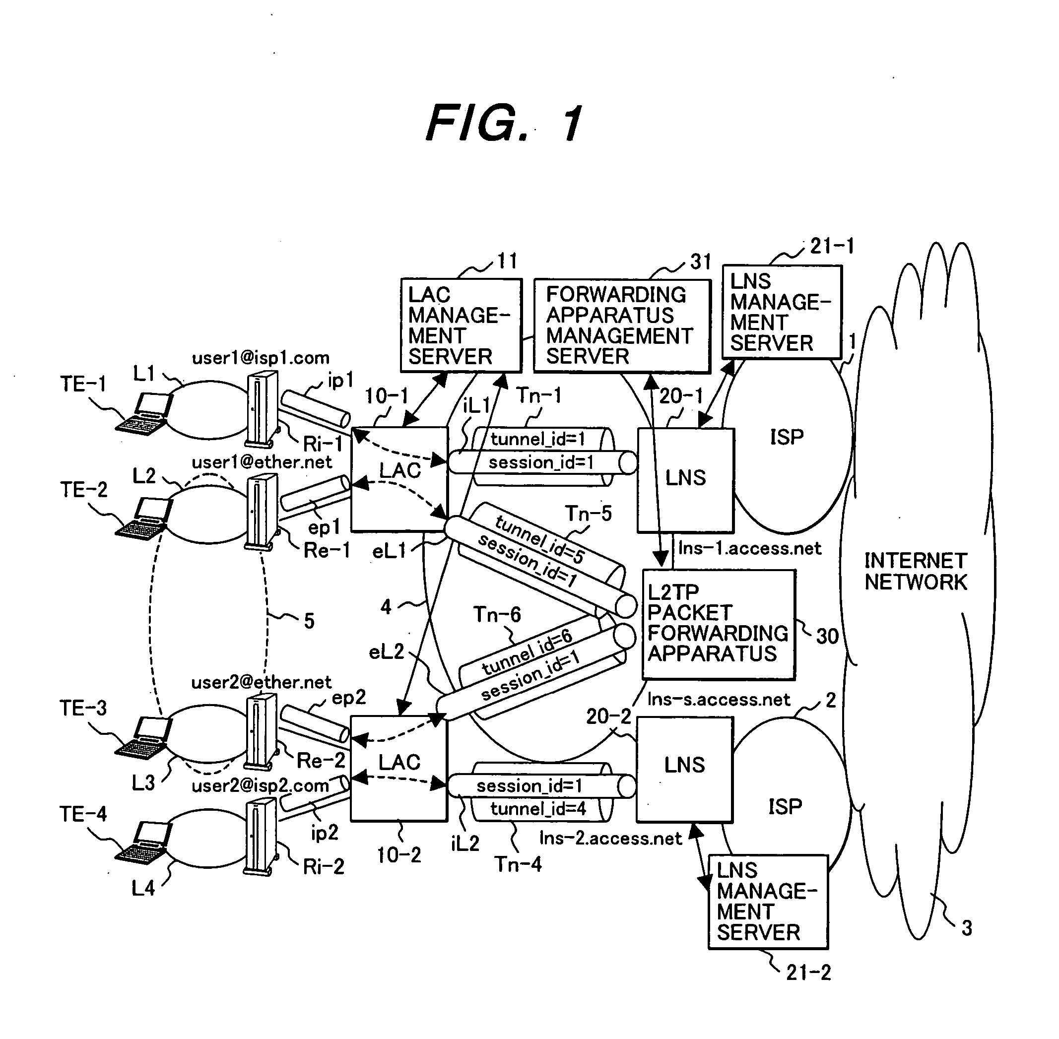
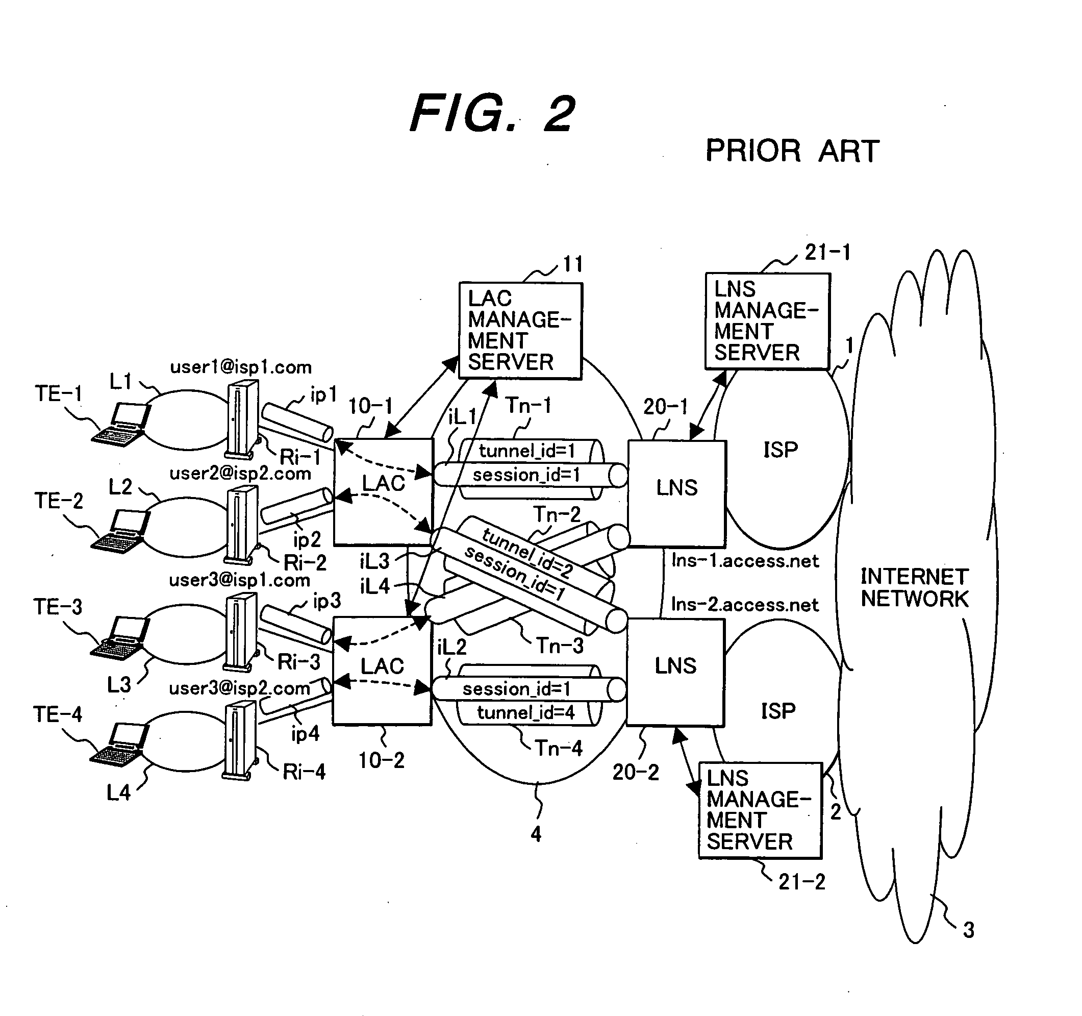
[0055]FIG. 1 is a network architecture diagram showing a first embodiment of a network to which the present invention is applied. Elements corresponding to those of the prior art example shown in FIG. 2 are assigned the same reference numbers or symbols in FIG. 1 and their explanation is not repeated. In L2TP, distinct values of tunnel ID and session ID can be set at each end point of a tunnel, but a tunnel ID / session ID pair shall be consistent at both ends of a tunnel here to simplify explanation. However, even if both ends of a tunnel have different values of tunnel ID and session ID, the operation principle which will be described hereinafter is unchanged.

[0056] When compared with FIG. 2, the network of FIG. 1 is distinctive in that an L2TP packet forwarding apparatus 30 which can forward L2TP packets received from an LAC to an L2TP session toward another LAC and a forwarding apparatus management server 31 provided in association with of this L2TP packet forwarding apparatus 30...

second embodiment

[0096]FIG. 11 is a network architecture diagram showing a second embodiment of the network to which the present invention is applied.

[0097] As compared with the network of the first embodiment shown in FIG. 1, a gateway Rie-1 provided with both the IP over PPP over PPPoE function and the Bridge over PPP over PPPOE function is used instead of the gateways Ri-1 and Re-1 in FIG. 1, and two LANs L1 and L2 in FIG. 1 are integrated into a single LAN L12. Between the gateway Rie-1 and the LAC 10-1, an IP over PPP over PPPOE tunnel ip1 and a Bridge over PPP over PPPOE tunnel ep1 are set up.

[0098]FIG. 12 shows an example of a configuration of the gateway Rie-1. The gateway Rie-1 is comprised of a plurality of input line interfaces 501 (501-1 to 501-m) and output line interfaces 502 (502-1 to 502-m) for connection to LANs and LACs 10, a packet forwarding processing unit 503 connected to these interfaces, and a controller 504 connected to the packet forwarding processing unit 503.

[0099] The...

third embodiment

[0110]FIG. 16 is a network architecture diagram showing a third embodiment of the network to which the present invention is applied.

[0111] While such a network architecture that the access network 4 and ISP networks 1 and 2 exist independently has been discussed in the first and second embodiments, the present invention is also applicable to a network architecture in which the access network 4 and ISP networks 1 and 2 are integrated.

[0112] In the case where the access network 4 and ISP networks 1 and 2 are integrated, the LNSs for connecting the access network and ISP networks are dispensed with, as shown in FIG. 16, and the access network 4 becomes an IP network having the same address space as the Internet 3. Wide area Ethernet service is implemented by the L2TP packet forwarding apparatus 30 as same as the first embodiment.

[0113] In the third embodiment, LAC-BASs 100-1 and 100-2 having the LAC function and Broadband Access Server (BAS) function are used instead of the LACs 10-...


PUM


Abstract

L2TP packet forwarding apparatus to be connected to at least two LACs (L2TP Access Concentrators) via L2TP sessions to receive packets transmitted from a gateway, which accommodates user terminals, in the form of a L2TP packet encapsulated in Bridge over PPP, has a lookup table indicating the correspondence of tunnel ID / session ID pairs to an identifier (VPN-IDs) of a wide area network to which a plurality of user terminals belong. The packet forwarding apparatus specifies an VPN-ID from the lookup table based on the tunnel ID and the session ID of a received packet and forwards, if it is confirmed that another tunnel ID / session ID pair associated with the same VPN-ID exists in the lookup table, the received packet to another L2TP session identified by the another tunnel ID / session ID pair in the form of a L2TP packet.

Description

CLAIM OF PRIORITY [0001] The present application claims priority from Japanese application serial No. 2004-354962, filed on Dec. 8, 2004, the content of which is hereby incorporated by reference into this application. BACKGROUND OF THE INVENTION [0002] (1) Field of the Invention [0003] The present invention relates to a packet forwarding apparatus and a communication network and, more particularly, to a packet forwarding apparatus and a communication network for Internet access suitable for wide area Ethernet service. [0004] (2) Description of the Related Art [0005] Conventionally, dedicated lines have been used to ensure layer 2 connectivity for communications between remote cites. However, since dedicated lines solely provide point-to-point connections, if the number of communication bases is great, the need for full-mesh connections between the communication bases has posed problems in network management and cost. [0006] Recently, attention has focused on wide area Ethernet servi...

Claims


Application Information

Patent Timeline
Patent Type & Authority Applications(United States)
IPC IPC(8): H04L12/56H04L45/74
CPCH04L12/2856H04L12/2859H04L12/2881H04L12/4633H04L12/4641
Inventor YOSHIMOTO, TETSUROYAMADA, MARIKOKAMATA, MASANORI
Owner HITACHI LTD
Why Eureka
Try Eureka