Communication system, delay insertion server, backup server and communication control apparatus

a communication system and delay insertion technology, applied in the field of communication system, delay insertion server, backup server and communication control apparatus, can solve the problems of a large amount of continuous packet loss of the type, the arrival of all packets, and the time of approximately several seconds to several tens of seconds for conventional multicast path control protocols

Inactive Publication Date: 2006-06-08
KDDI CORP
View PDF17 Cites 42 Cited by
  • Summary
  • Abstract
  • Description
  • Claims
  • Application Information

AI Technical Summary

Benefits of technology

[0021] A twelfth aspect of the present invention is a communication control apparatus which is included in a communication system which uses an IP network to support broadcast-type multicast packet communications, including: a first unit which receives a probe multicast packet which same fixed delay time as that of a main multicast packet is inserted to, and which is distributed via a same path as the main multicast packet which is distributed in a broadcast format, from the IP network; a second unit which checks communication condition of the main multicast packet based a reception interval of the probe multicast packet; a third unit which, when a communication break in the main multicast packet is detected, receives a synchronism backup multicast packet which is copied from the main multicast packet and a delay backup multicast packet which is copied from the main multicast packet and which is generated by inserting a same fixed delay time to the copied packet; and a fourth unit which uses the received backup multicast packets to generate a backup main multicast packet which is distributed via the same path as the main multicast packet, and transmits the backup main multicast packet to the IP network.
[0022] A thirteenth aspect of the present invention is the above described communication control apparatus, further including a transmission queue which stores the received synchronism backup multicast packet; a match detection unit which detects reception of a delay backup multicast packet which matches the received synchronism backup multicast packet; and a transmission control unit which, when a communication break in the multicast packet is d...

Problems solved by technology

However, even if a high-reliability IP network is constructed using a router (L3 {Layer-3}) with a redundant configuration, a time of approximately several seconds to several tens of seconds is required for conventional multicast path control protocols due to dynamic changes in the multicast...

Method used


Image

  • Communication system, delay insertion server, backup server and communication control apparatus
  • Communication system, delay insertion server, backup server and communication control apparatus
  • Communication system, delay insertion server, backup server and communication control apparatus

Examples


Embodiment Construction

[0031] An embodiment of this invention will be explained with reference to the diagrams.

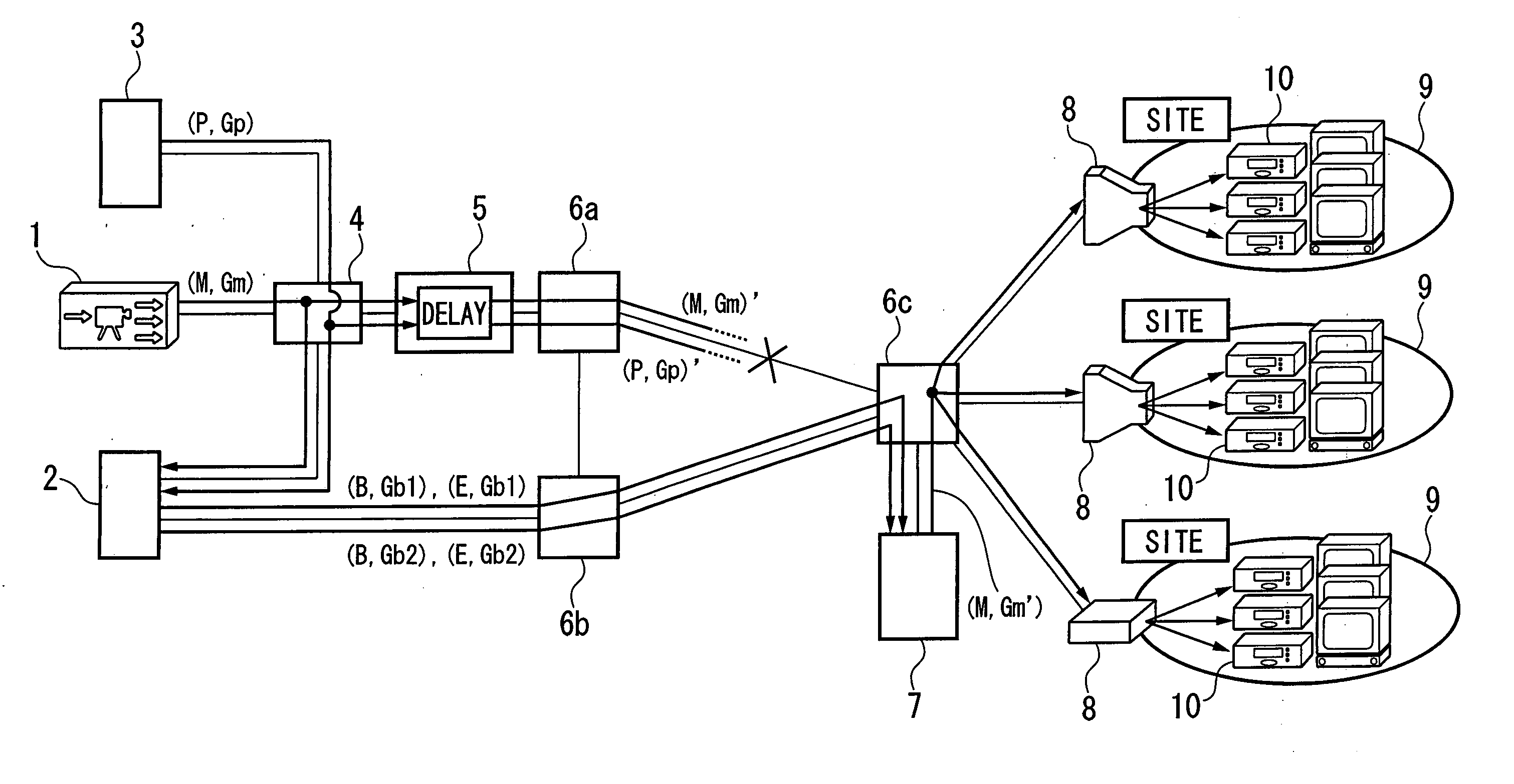
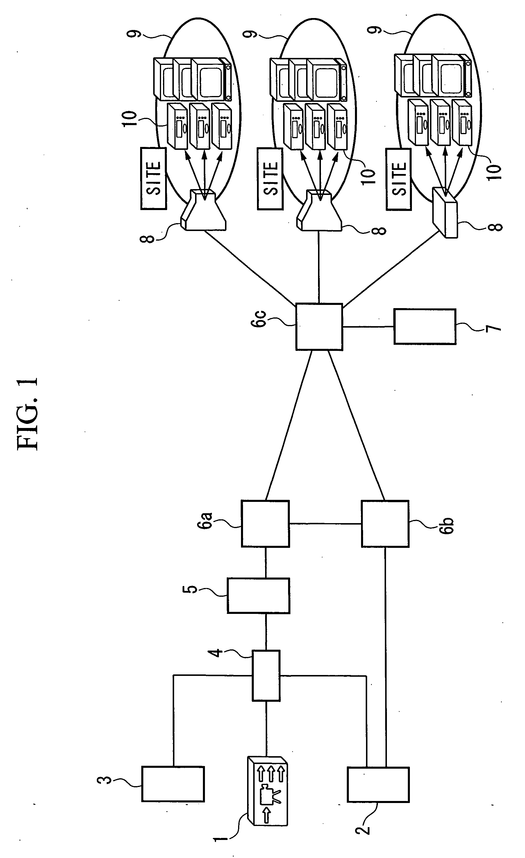
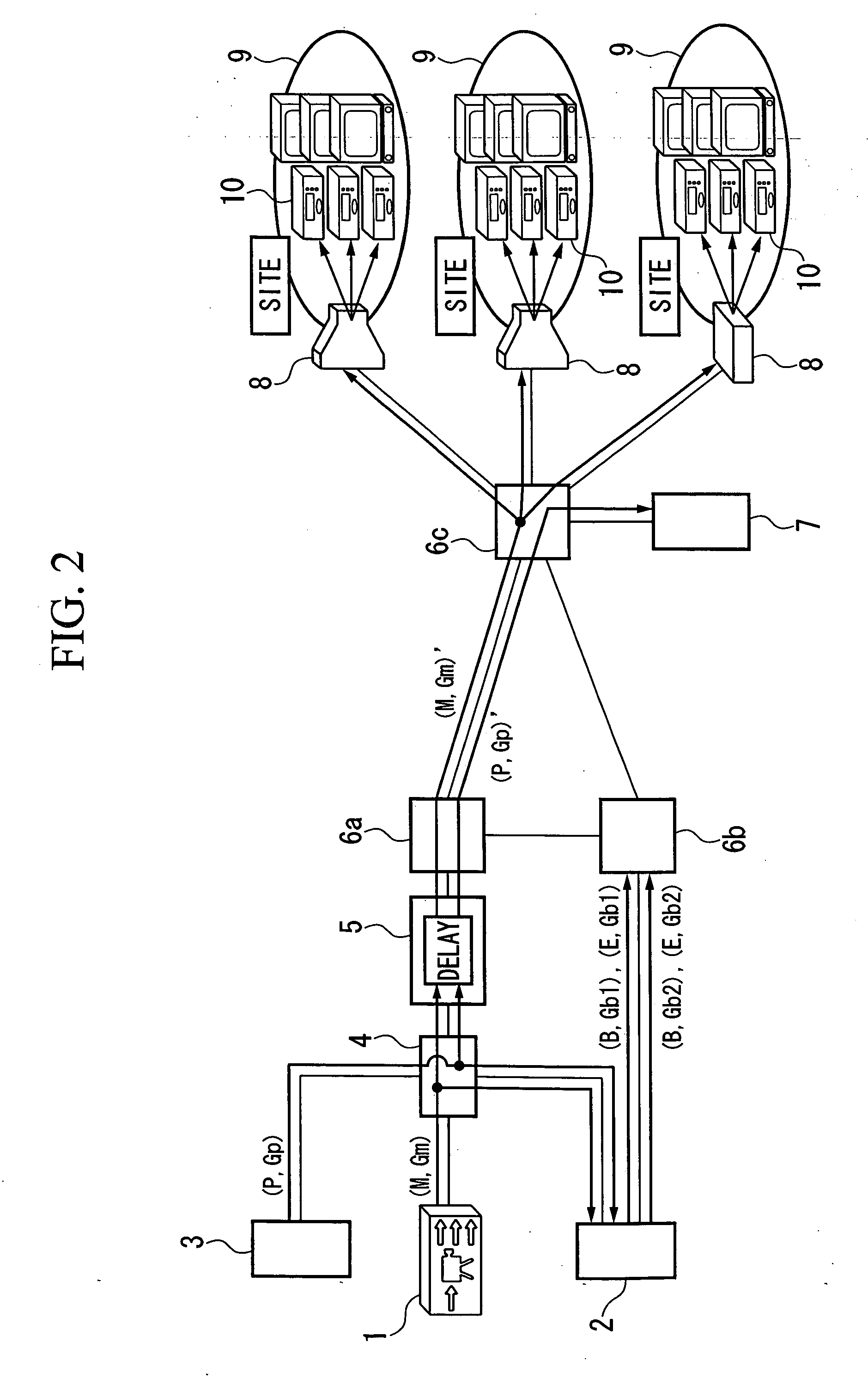
[0032]FIG. 1 is a schematic diagram of the configuration of a broadcast-type multicast communication system according to an embodiment of this invention. This system implements a broadcast-type multicast communication service.

[0033] In FIG. 1, a broadcast distribution server 1, a backup server 2, and a probe transmission server 3 are connected to a Layer-2 (L2) switch 4 incorporating a TAP function (hereinafter abbreviated as “L2 switch”). A delay insertion server 5 is provided between the L2 switch 4 and a Layer-3 (L3) switch 6a, and connects to both the switches 4 and 6a.

[0034] The backup server 2, the probe transmission server 3, and the optical path divider 5 are installed near the broadcast distribution server 1. The probe transmission server 3 is provided on the same subnetwork as the broadcast distribution server 1.

[0035] L3 switches 6a, 6b, and 6c are mutually connected, and form an I...


PUM


Abstract

A communication system includes a probe transmission server 3 which transmits at fixed intervals of time a probe multicast packet distributed along the same path as a main multicast packet, a delay insertion server 5 which appends the same fixed delay time to each of the main multicast packet and the probe multicast packet, a backup server 2 which generates synchronism and delay backup multicast packets from the main multicast packet and transmits them, and a communication control device 7 which determines the communication of the main multicast packet based on a reception interval of the probe multicast packet, generates a backup main multicast packet from the backup multicast packet when a communication break is detected, and transmits it. The communication system, upon implementing a broadcast-type multicast service, enhances compensation of communication breaks when detecting and recovering from a fault in an IP network, and reduces the network traffic.

Description

BACKGROUND OF THE INVENTION [0001] 1. Field of the Invention [0002] The present invention relates to a communication system which distributes a continuous stream packet from at least one server to multiple clients via an IP network, a delay insertion server, a backup server, and a communication control apparatus. [0003] Priority is claimed on Japanese Patent Application No. 2004-349665, filed Dec. 2, 2004, the content of which is incorporated herein by reference. [0004] 2. Description of Related Art [0005] To implement a service such as video distribution, a multicast is defined in an open systems interconnection (OSI) Layer-3 internet protocol (IP), and various types of protocol corresponding thereto are mounted and executed (e.g. see Non-Patent Literature 1: Beau Williamson, “IP Multicast Network Development Guide Vol. 1” Softbank Publishing Corp., Jul. 3, 2001.). Various types of highly reliable multicast communication protocols for supporting a multicast without losing data have...

Claims


Application Information

Patent Timeline
IPC IPC(8): H04L12/26H04J3/26H04L45/16H04L45/586
CPCH04L12/1863H04L12/2697H04L43/50
Inventor HASEGAWA, TERUYUKIHASEGAWA, TORU
Owner KDDI CORP
Why Eureka
Try Eureka