Optical transceiver for transmitting light source control information and optical network using the same

Inactive Publication Date: 2006-06-08
ELECTRONICS & TELECOMM RES INST
View PDF3 Cites 16 Cited by
  • Summary
  • Abstract
  • Description
  • Claims
  • Application Information

AI Technical Summary

Benefits of technology

[0021] Therefore, the present invention has been made in view of the above problems, and it is an object of the present invention to provide an optical transceiver for transmitting light source control information and an optical network using the same, which are implemented so as to allow a subscriber ONT and/or a telephone office OLT to transmit light source control information by incorporating it into a Subcarri...

Problems solved by technology

However, the conventional OBI reduction methods reduce OBI by directly controlling the light source or using a device for controlling the light source.
Since OBI occur...

Method used


Image

  • Optical transceiver for transmitting light source control information and optical network using the same
  • Optical transceiver for transmitting light source control information and optical network using the same
  • Optical transceiver for transmitting light source control information and optical network using the same

Examples


Embodiment Construction

[0031] Now, preferred embodiments of the present invention will be described with reference to the accompanying drawings. In the drawings, the same or similar elements are denoted by the same reference numerals even though they are depicted in different drawings.

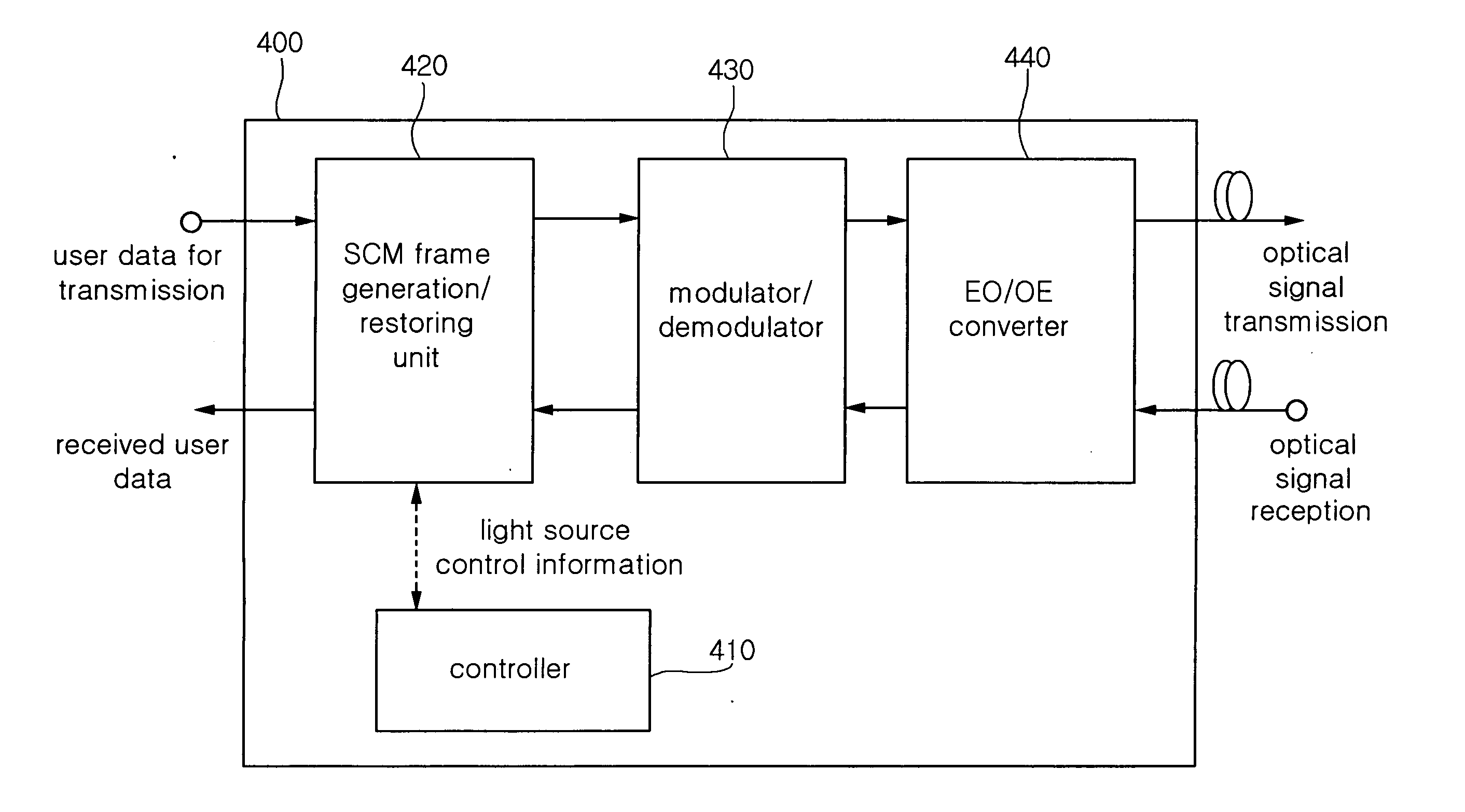
[0032]FIG. 4 is a block diagram of an optical transceiver according to the present invention.

[0033] The optical transceiver according to the present invention is applied to a telephone office OLT and a subscriber ONT. As shown in FIG. 4, the optical transceiver 400 includes a controller 410, an SCM frame generation / restoring unit 420, a modulator / demodulator 430, and an EO / OE converter 440. The controller 410 controls transmission of light source control information used for Optical Beat Interference (OBI) control, and collects received light source control information to perform light source control. The SCM frame generation / restoring unit 420 generates an SCM frame (SCM-FM) containing light source control information rec...


PUM


Abstract

An optical transceiver for transmitting light source control information, which is applied to a Subcarrier Multiplexing optical network, is disclosed. The optical transceiver includes a controller, an SCM frame generation/restoring unit, a modulator/demodulator, and an EO/OE converter. The controller controls transmission of light source control information or collects received light source control information. The SCM frame generation/restoring unit generates an SCM frame containing light source control information received from the controller. The modulator/demodulator modulates an SCM frame generated by the SCM frame generation/restoring unit into a signal suitable for transmission. The EO/OE converter converts a transmission signal modulated by the modulator/demodulator into an optical signal and transmits the optical signal through an optical fiber. An optical network having a telephone office OLT and subscriber ONTs, each having the optical transceiver, is also disclosed.

Description

RELATED APPLICATION [0001] The present application is based on, and claims priority from, Korean Application Number 2004-102607, filed Dec. 07, 2004, the disclosure of which is incorporated by reference herein in its entirety. BACKGROUND OF THE INVENTION [0002] 1. Field of the Invention [0003] The present invention relates to an optical transceiver that is applied to an optical network such as a Passive Optical Network (PON) and a Subcarrier Multiplexing over Wavelength Division Multiplexing (WDM) PON, and more particularly to an optical transceiver for transmitting light source control information and an optical network using the same, which are implemented so as to allow an Optical Network Terminal (ONT) at the subscriber side (hereinafter referred to as a “subscriber ONT”) and / or an Optical Line Terminal (OLT) at the communication company side (hereinafter referred to as a “telephone office OLT”) to transmit light source control information by incorporating it into an SCM frame, ...

Claims


Application Information

Patent Timeline
IPC IPC(8): H04B10/00
CPCH04B10/40H04J14/0226H04J14/0282H04J14/0298H04J14/0247H04J14/0252H04L12/28
Inventor LEE, CHUL SOOKIM, BYOUNG WHIJUNG, EUI SUKJANG, SEUNG HYUN
Owner ELECTRONICS & TELECOMM RES INST
Why Eureka
Try Eureka