
Tubular orthodontic arch wire

a tubular, orthodontic technology, applied in the field of tubular orthodontic arch wires, can solve the problems of brackets falling off from teeth, patient experience extreme discomfort, and orthodontic appliances are too strong to withstand, so as to reduce friction, reduce force levels, and reduce the effect of for

Inactive Publication Date: 2006-06-08
VOGT WILLIAM
View PDF10 Cites 7 Cited by
  • Summary
  • Abstract
  • Description
  • Claims
  • Application Information

AI Technical Summary

Benefits of technology

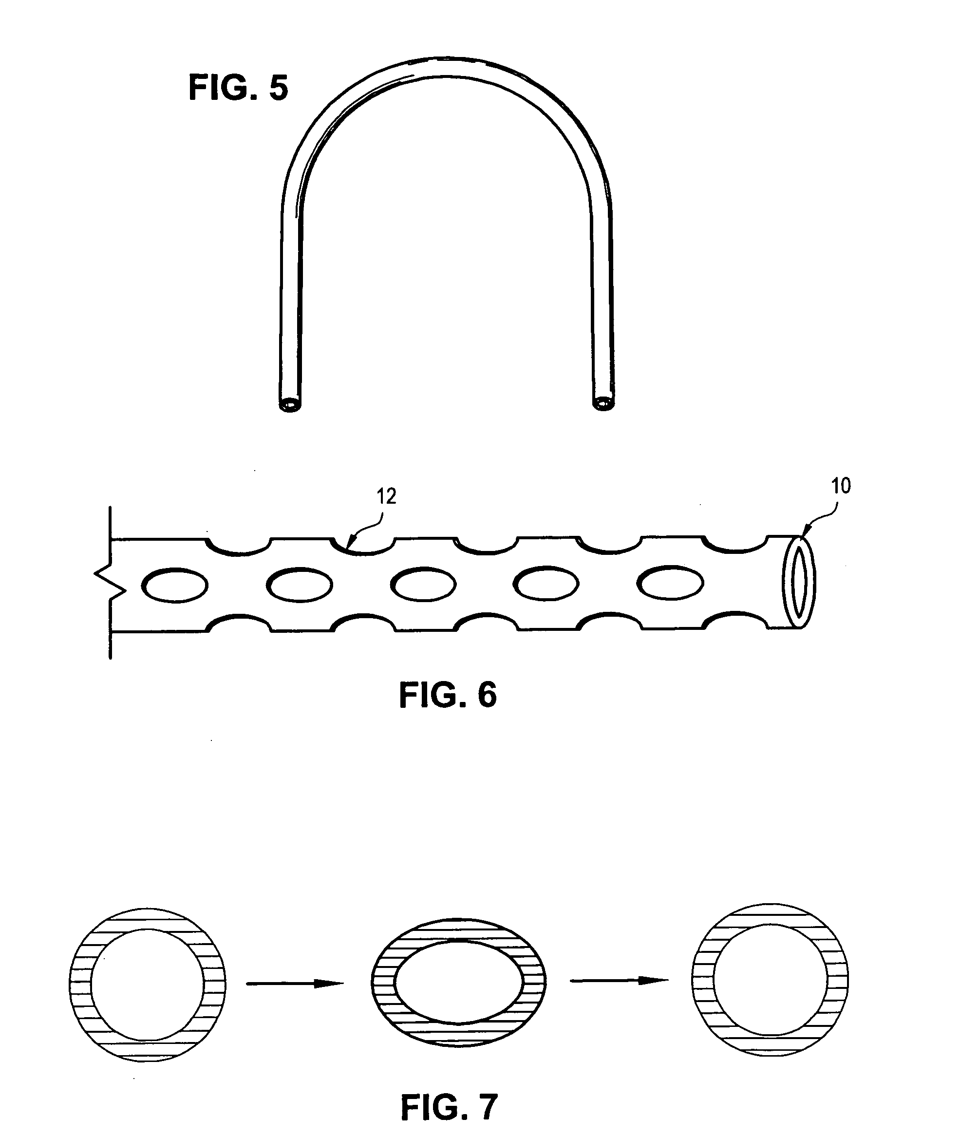
"The present invention provides an orthodontic arch wire that is made of a tubular length of material composed of a super-elastic alloy. The arch wire can be perforated to further reduce its restorative force. The arch wire has the benefit of providing reduced force levels over solid or multi-stranded wires of the same exterior dimensions. It can provide a consistent continuous force over a long period and over a large range of stress. It can be designed in different shapes to fill the orthodontic bracket slots as fully as possible. It can create a smooth outside wall to reduce friction for easier tooth movement. It can be compressed in the direction of its cross-sectional dimension and can recover its original shape."

Problems solved by technology

Even if it were possible to get this size wire inserted into the brackets, the force would be too great for the orthodontic appliances to withstand and the brackets would break off from the teeth.
In addition, at this force level the patient would experience extreme discomfort.
Gold wires were not very effective due to the softness of the metal allowing the wires to deform easily.
Although the stiffness of the wire was reduced and the resilience increased compared to solid stainless steel wires, the force level was still higher than ideal and the wires still had a tendency to permanently deform when they were moderately stressed.
Although multi-stranded super-elastic wires reduce the force compared to solid wires, they are even more prone to breakage and fraying than stainless steel multi-stranded wires.
Even after the above inventions, the force level of existing arch wires remains too high for a full-size wire to fully engage the slots of orthodontic brackets without either breaking the brackets off of the teeth or causing extreme patient discomfort.
While good in theory, these devices have shown to be impractical.

Method used


Image

  • Tubular orthodontic arch wire
  • Tubular orthodontic arch wire
  • Tubular orthodontic arch wire

Examples


Embodiment Construction

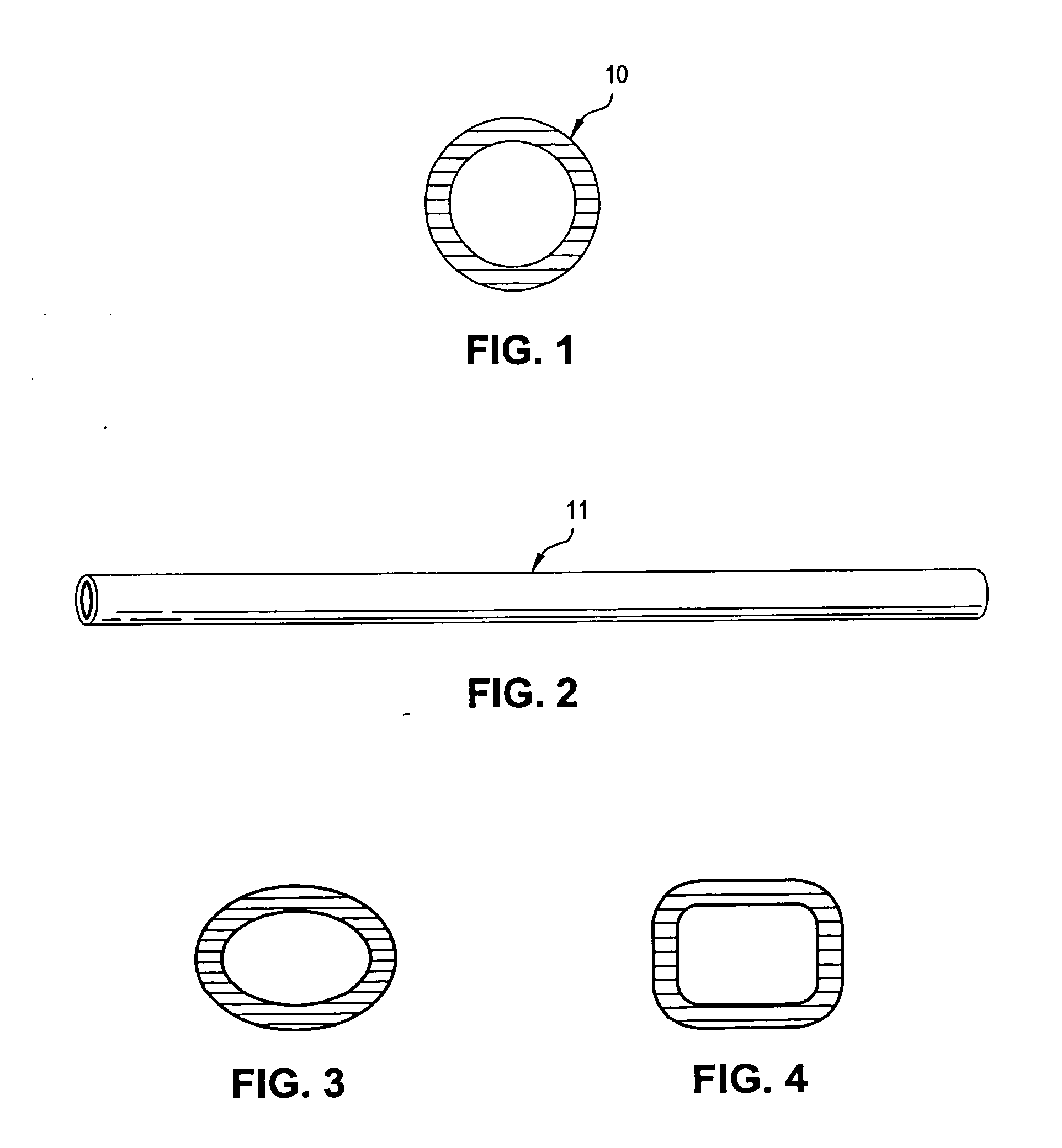
[0020] The preferred embodiment is a thin walled tube as is depicted in FIGS. 1 and 2. The tube is preferably made from a super-elastic, shape memory material, preferably nickel titanium alloy that is shaped in the form of a dental arch dimensioned to fit into the bracket slots and tubes of orthodontic appliances. The dimensions range from a round tube with an outside dimension of 0.012-inch diameter to as large as a rectangular tube with outside dimensions of 0.025 by 0.030 inches. The arch tube may be made in different shapes such as but not limited to round as in FIG. 1, oval as seen in FIG. 3, or rectangular as seen in FIG. 4. The tube can easily be manufactured in a round configuration but can later be reshaped through compression and heat treatment into different shapes. Alternatively, a mandrel may be inserted into the tube and the tube heat-treated to change its shape. The tube may have multiple shapes within the same tube such as oval in the middle and round toward the ends...


PUM

PropertyMeasurementUnit
diameteraaaaaaaaaa
lengthaaaaaaaaaa
super-elasticaaaaaaaaaa

Abstract

A length of tubular material of unitary construction is formed into the approximate shape of a human dental arch for use as an orthodontic arch wire. The tubular material is composed of a super-elastic nickel titanium alloy which may also have shape memory. The cross-sectional shape of the arch wire tube can be round, oval, square, or rectangular. The preferred thickness of the tube is preferably 20 percent of its outside diameter and the tube may be perforated to alter its performance.

Description

FIELD OF THE INVENTION [0001] The present invention relates to orthodontic wires for aligning human teeth. More specifically, it relates to the use of thin-walled tubing having reduced stiffness for use as orthodontic arch wires. Additional modifications may be employed to reduce stiffness further. BACKGROUND OF THE INVENTION [0002] Orthodontic treatment is the movement of poorly positioned teeth into their correct positions. This treatment usually requires the attachment of bands or brackets to the teeth. In order for the teeth to move, a wire is attached to the brackets or bands through which force can be transmitted to the teeth that need to be straightened. [0003] When the orthodontic bands and brackets are initially attached to malpositioned teeth, a fairly flexible wire shaped in the form of an ideal dental arch is usually placed into the slots and the tubes of the bands and brackets. The arch wire can act as a track to guide the movements of the teeth along the wire when elas...

Claims


Application Information

Patent Timeline
Patent Type & Authority Applications(United States)
IPC IPC(8): A61C3/00
CPCA61C7/20A61C2201/007
Inventor VOGT, WILLIAM
Owner VOGT WILLIAM
Learn More