Wide blade, axial flow pump

a technology of axial flow and wide blades, which is applied in the direction of piston pumps, prostheses, therapy, etc., can solve the problems of reducing the torque capacity and efficiency of motors, and internal blood pumps are also subject to anatomical compability design constraints,

Active Publication Date: 2006-06-08
HEARTWARE INC
View PDF36 Cites 64 Cited by
  • Summary
  • Abstract
  • Description
  • Claims
  • Application Information

AI Technical Summary

Problems solved by technology

Both of these approaches tend to reduce the motor torque capacity and efficiency, and they use mechanical rotor support involving abutting surfaces that move relative to each other in rotation.
Internally located b

Method used


Image

  • Wide blade, axial flow pump
  • Wide blade, axial flow pump
  • Wide blade, axial flow pump

Examples


Embodiment Construction

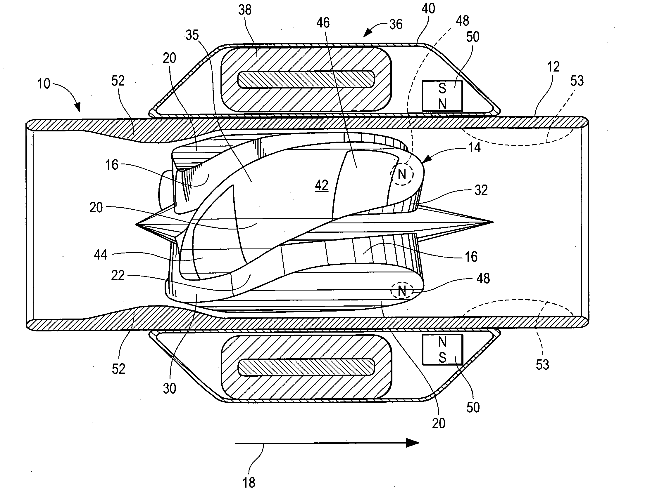
[0007] In accordance with this invention a blood pump is provided which comprises a pump housing; and a rotor positioned in the housing and comprising an impeller having a hydrodynamic surface for pumping blood. A motor is provided, the motor having a plurality of magnetic poles of a magnet or magnets carried by the impeller. A motor stator is provided, which includes an electrically conductive coil located adjacent to or within the housing.

[0008] Hydrodynamic bearing surfaces may also be present, being symmetrically located around the impeller. The term “hydrodynamic bearing surfaces” implies that the bearing surface is acting against fluid to impart forces to the rotor, which helps to position the rotor.

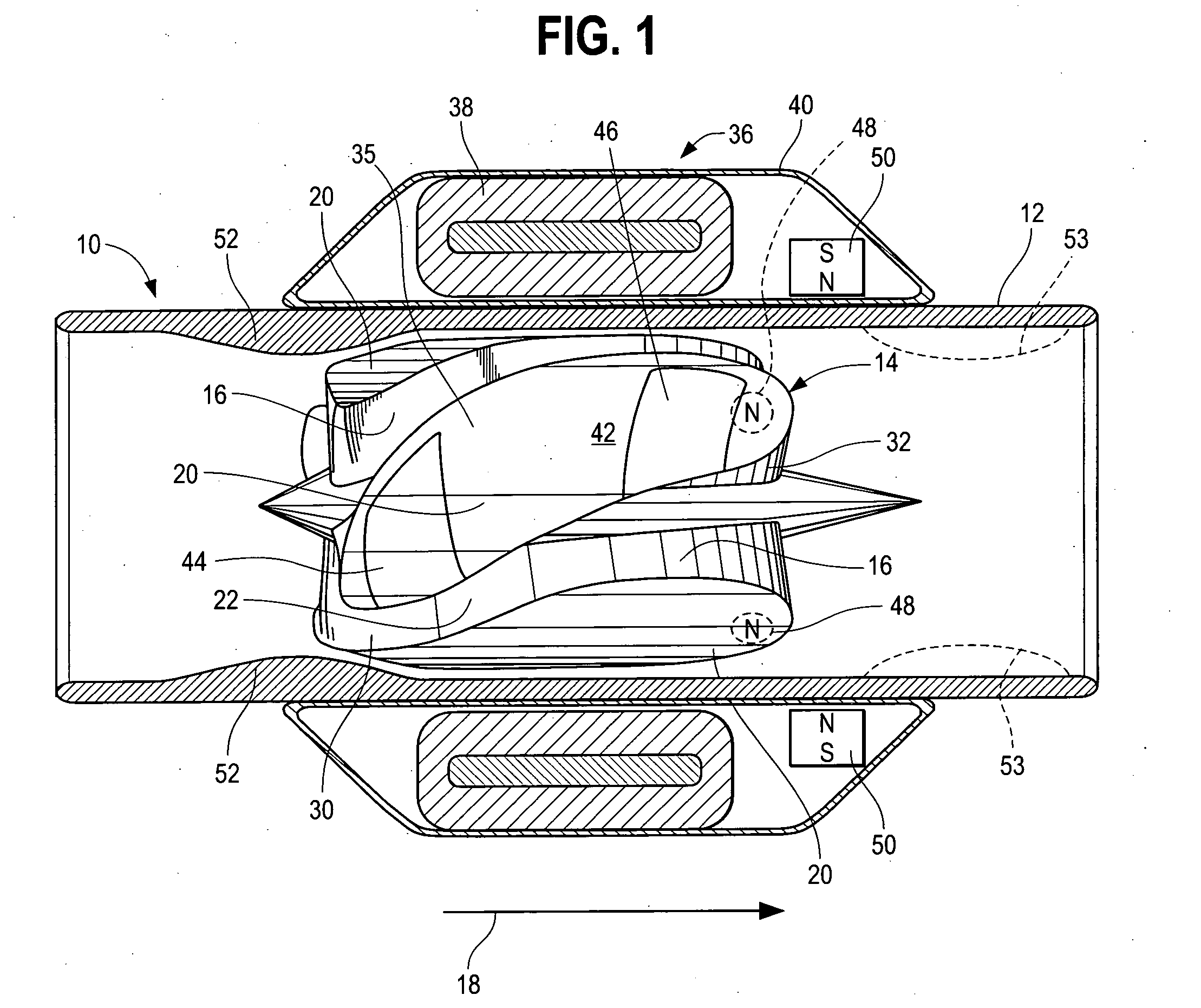
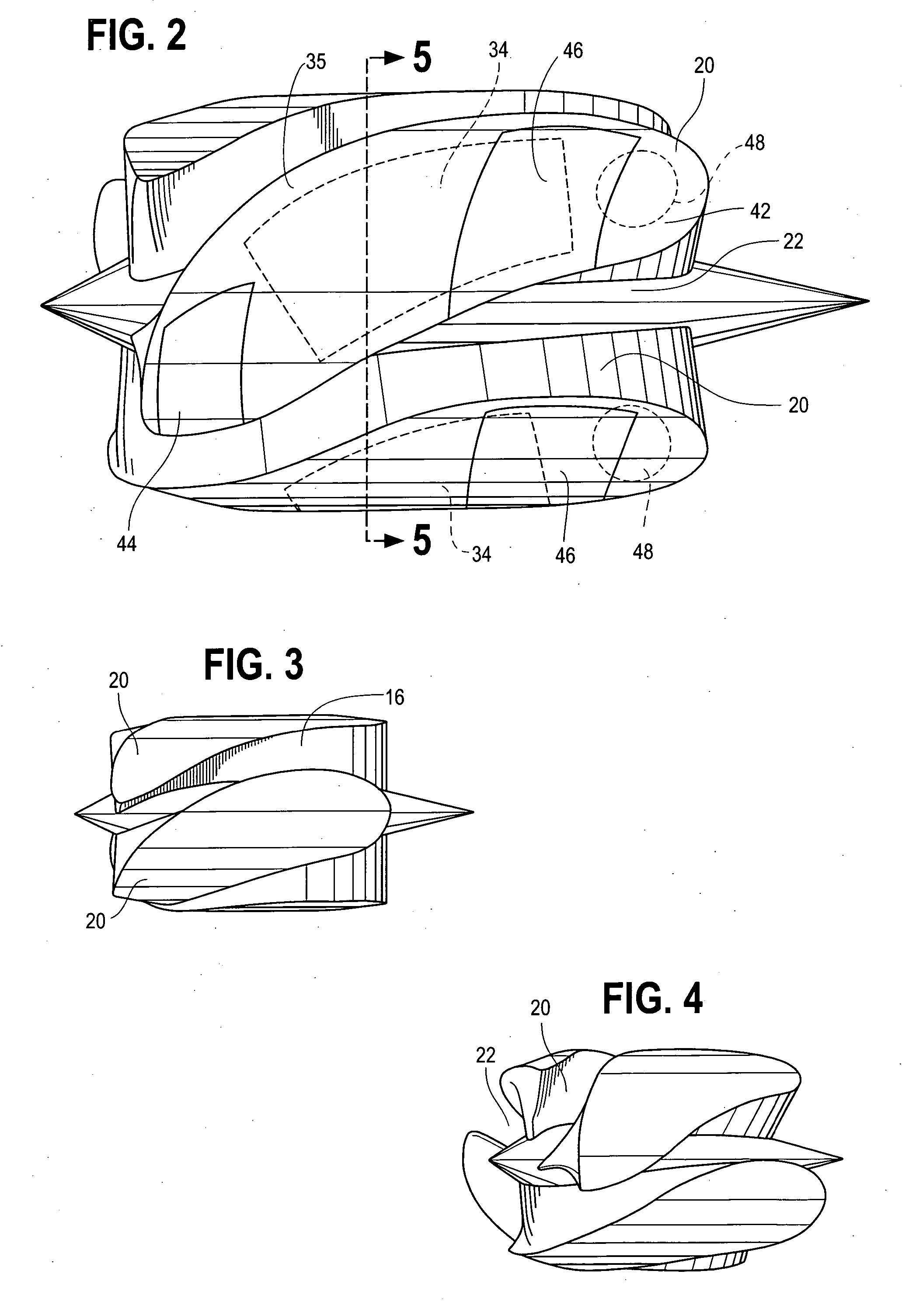
[0009] The impeller comprises radially outwardly extending, blade-like projections that define generally longitudinally extending spaces between the projections. The projections are shaped to form curves in the spaces of a shape tending to drive blood in an axial direction as the...


PUM


Abstract

A blood pump comprises a pump housing; a rotor positioned in the housing and comprising an impeller having a hydrodynamic surface for pumping blood; and a motor including a plurality of magnets carried by the impeller, plus a rotor stator, including an electrically conductive coil located adjacent to or within the housing. The impeller comprises radially outwardly extending, bladelike projections that define generally longitudinally extending spaces between the projections. The shape of the projections and the spaces therebetween tend to drive blood in the spaces in an axial direction as the impeller is rotated. The spaces collectively have a total width along most of their lengths at the radial periphery of the rotor, that is substantially equal to or less than the collective width of the projections along most of their lengths at the radial periphery. Thus, the bladelike projections are thicker, achieving significant advantages.

Description

BACKGROUND OF THE INVENTION [0001] The known axial flow pumps for blood have the advantage of narrow width, when compared with radial flow pumps. Axial flow pumps typically have a cylindrical housing with an inlet at one end, an outlet at the opposite end, and a rotor within the housing which has impeller blades attached to the rotor. Thus, as the rotor rotates, the blades add work to the fluid, propelling the fluid through one end of the housing. [0002] A suspension system is provided to maintain the rotor in desired position within the housing, and a motor is provided to spin the rotor. Blood flows between the blades, being propelled through the pump by hydrodynamic forces transferred by the blade surfaces. [0003] The blood then leaves the pump, flowing parallel to the axis of rotation of the rotor. Typically in the prior art, the rotor is suspended by mechanical bearings or bushings, with a rotor shaft protruding through the pump housing to a motor drive mechanism. Magnetic suspe...

Claims


Application Information

Patent Timeline
IPC IPC(8): A61N1/362
CPCA61M1/101A61M1/1017A61M60/82A61M60/824A61M60/422A61M60/148A61M60/546A61M60/237A61M60/523A61M60/122
Inventor LAROSE, JEFFREY A.SHAMBAUGH, CHARLES R. JR.
Owner HEARTWARE INC
Why Eureka
Try Eureka