Motor and its stator structure

A motor stator and stator technology, applied in the field of motors, can solve the problems of reducing the rotational torque of the rotor and reducing the induction area of ​​the permanent magnet, and achieve the effects of increasing the magnetic flux, increasing the area, and increasing the induction area.

Inactive Publication Date: 2009-11-18
HONG FU JIN PRECISION IND (SHENZHEN) CO LTD +1
View PDF3 Cites 0 Cited by
  • Summary
  • Abstract
  • Description
  • Claims
  • Application Information

AI Technical Summary

Problems solved by technology

[0003] Although the above structure can cause different magnetic forces on both sides of the upper and lower pole pieces 211, 221 to drive the rotor to rotate in a predetermined direction, the upper and lower pole pieces 211, 221 will be reduced due to their truncated angles 212, 222. The induced area of ​​the permanent magnet of the rotor reduces the rotational torque of the rotor, so it needs to be improved

Method used


Image

  • Motor and its stator structure
  • Motor and its stator structure
  • Motor and its stator structure

Examples


Embodiment Construction

[0016] The present invention will be further described below with reference to the accompanying drawings and embodiments.

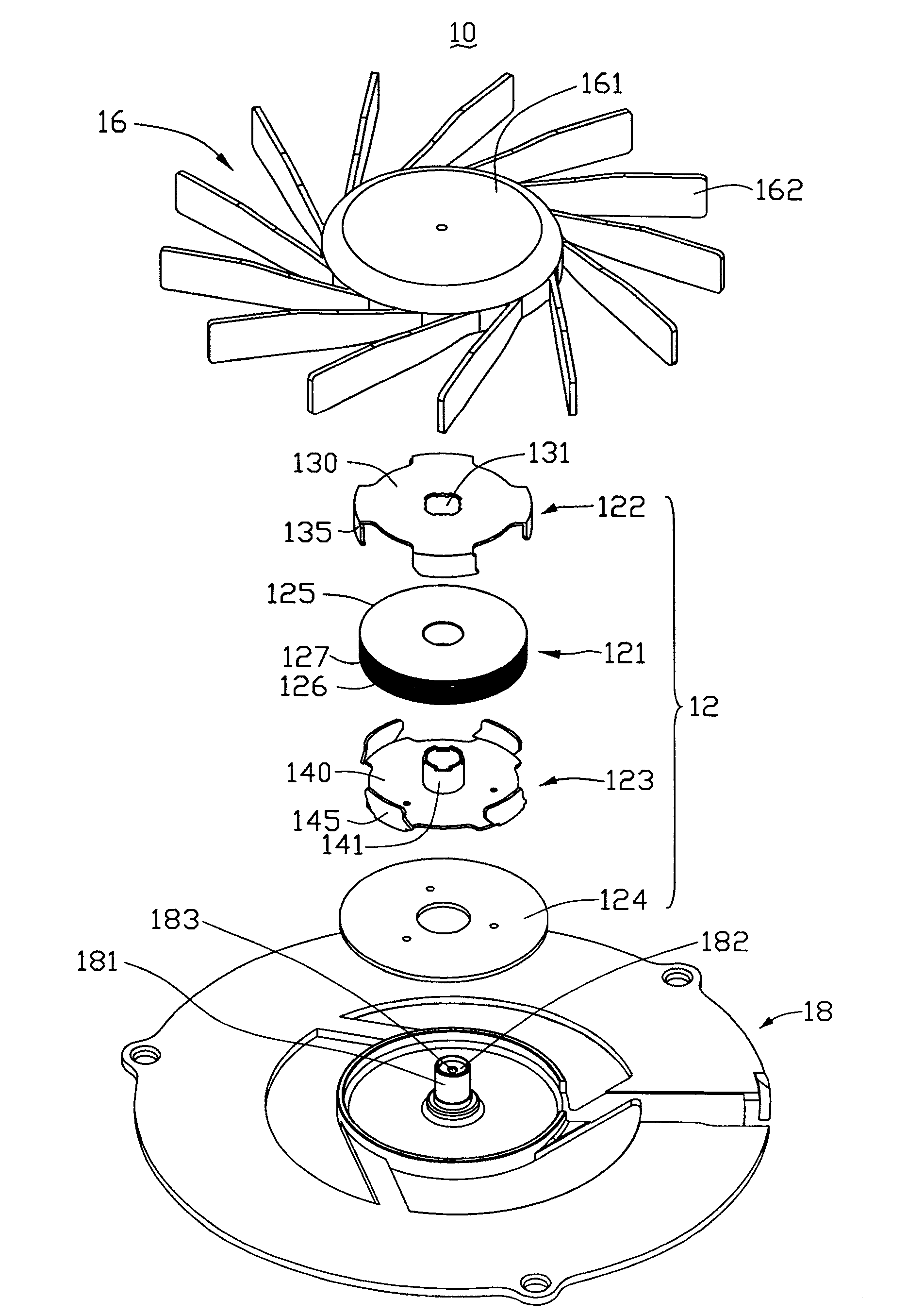
[0017] figure 1 Shown is an exploded perspective view of a preferred embodiment of the motor 10 of the present invention. The motor 10 includes a stator group 12 and a rotor 16. The stator group 12 is disposed on a housing 18, and the rotor 16 is covered by the rotor 16. on the stator group 12.

[0018] The rotor 16 includes a hub 161 and a plurality of blades 162 surrounding the hub 161. Permanent magnets (not shown) are arranged in the hub 161. The center of the hub 161 extends downward to form a rotating shaft (not shown). A central column 181 is arranged in the middle of the seat 18 and is penetrated through the stator group 12 . A bearing 182 is arranged in the central column 181 , and a shaft hole 183 is arranged in the central axis of the bearing 182 for the shaft of the rotor 16 to pass through to support the rotation of the rotor 16 . .

[00...


PUM


Abstract

A motor stator structure, including a stator group, the stator group includes a coil base and first and second magnetic pole pieces respectively arranged at both ends of the coil base, the first magnetic pole piece is bent and extended toward the second magnetic pole piece to form A plurality of first pole pieces, the second pole pieces are bent and extended toward the first pole pieces to form a plurality of second pole pieces, the first and second pole pieces are arranged alternately along the circumferential direction of the stator group, and the adjacent first pole pieces 1. On the side of one of the second pole pieces, a first tongue protrudes outward along the circumferential direction of the stator group, and the side of the other pole piece corresponds to the first tongue along the circumference of the stator group. The direction is inwardly recessed to form a first truncated corner.

Description

technical field [0001] The present invention relates to a motor, in particular to a motor and its stator structure. Background technique [0002] With the continuous development of science and technology and modern industry, motors have been widely used in products such as fans. Figure 7 Shown is a schematic diagram of the structure of the pole pieces of the fan motor stator in the prior art. In this structure, the ends of the upper and lower pole pieces 211 and 221 on the same side of the upper and lower pole pieces 21 and 22 are bent and extended, respectively. The truncated corners 212 and 222 make the areas on both sides of the upper and lower pole pieces 211 and 221 induced by the permanent magnets of the rotor (not shown) different, so that the magnetic forces excited on both sides of the upper and lower pole pieces 211 and 221 are different. The rotor thus rotates in a predetermined direction. [0003] In the above structure, different magnetic forces can be generat...

Claims


Application Information

Patent Timeline
Patent Type & Authority Patents(China)
IPC IPC(8): H02K1/12H02K3/04H02K11/00H02K29/00
Inventor 杨志豪
Owner HONG FU JIN PRECISION IND (SHENZHEN) CO LTD
Why Eureka
Try Eureka