Control device for starting LCD power supply

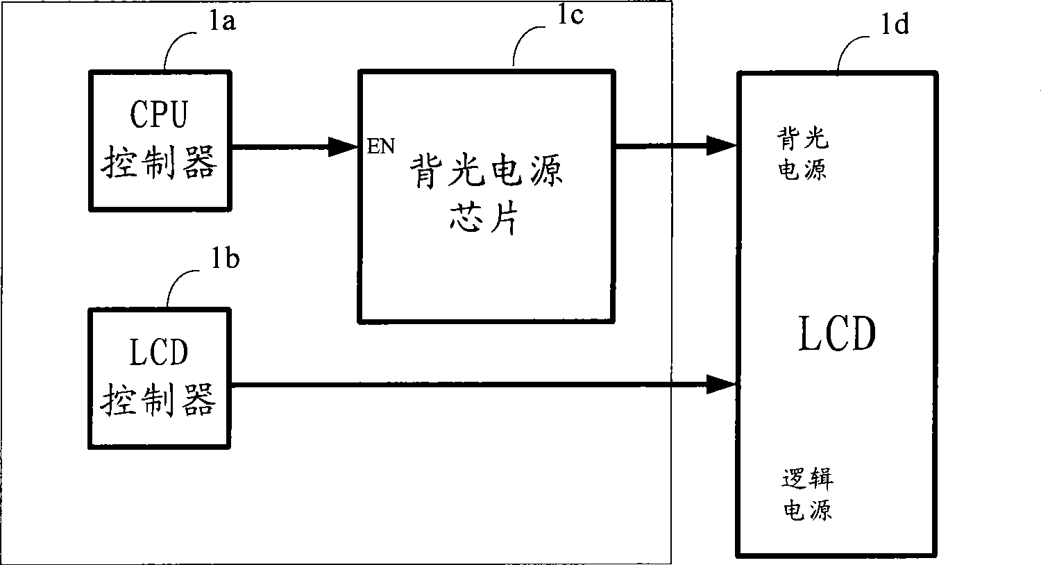
A technology for starting a power supply and a control device, which is applied in the field of control and can solve problems such as the inability to clarify and ensure the correct sequence of the logic power supply and the backlight power supply.

Inactive Publication Date: 2009-05-27
SANY HEAVY IND CO LTD (CN)
View PDF0 Cites 13 Cited by
  • Summary
  • Abstract
  • Description
  • Claims
  • Application Information

AI Technical Summary

Problems solved by technology

[0008] However, using the control device described in the prior art, the backlight power supply is enabled according to the order in which the internal programs of the CPU controller 1a are executed. Since the CPU controller 1a cannot obtain the logic power supply of the LCD 1d and the status information of the LCD controller 1b, it cannot It is clear whether the LCD 1d logic power supply is powered on and the LCD controller 1b startup is completed when the backlight is turned on, so it cannot be guaranteed that the LCD 1d logic power supply and the backlight power supply are started in the correct order

Method used


Image

  • Control device for starting LCD power supply
  • Control device for starting LCD power supply
  • Control device for starting LCD power supply

Examples


Embodiment 2

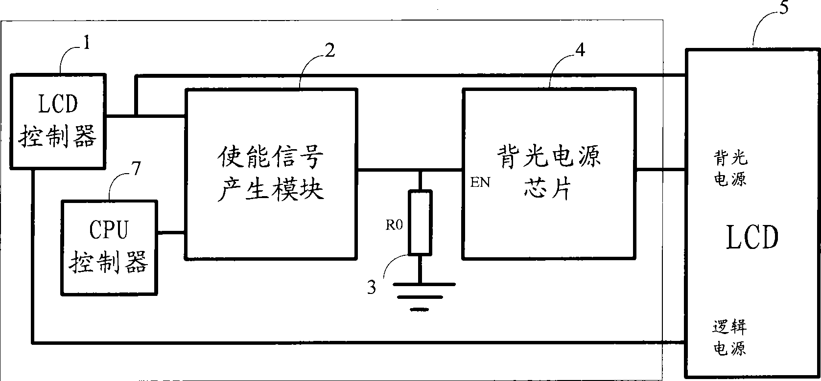
[0061] The difference between the second embodiment and the first embodiment is that the control device further includes: a CPU controller 7 .

[0062] The power interface of the LCD controller 1 is connected to the logic power supply of the LCD 5 . The output port of the LCD controller 1 is connected to the first input end of the enable signal generating module 2 and the control signal input end of the LCD 5 . One output port of the CPU controller 7 is connected to the second input port of the enable signal generating module 2 . The output terminal of the enable signal generating module 2 is connected to the enable pin of the backlight power supply chip 4 . The output terminal of the backlight power supply chip 4 is connected to the backlight power supply of the LCD 5 . The pull-down resistor R03 is connected between the enable pin of the backlight power supply chip 4 and the ground.

[0063] When the LCD 5 is turned on and powered on, the LCD controller 1 is started by th...

Embodiment 3

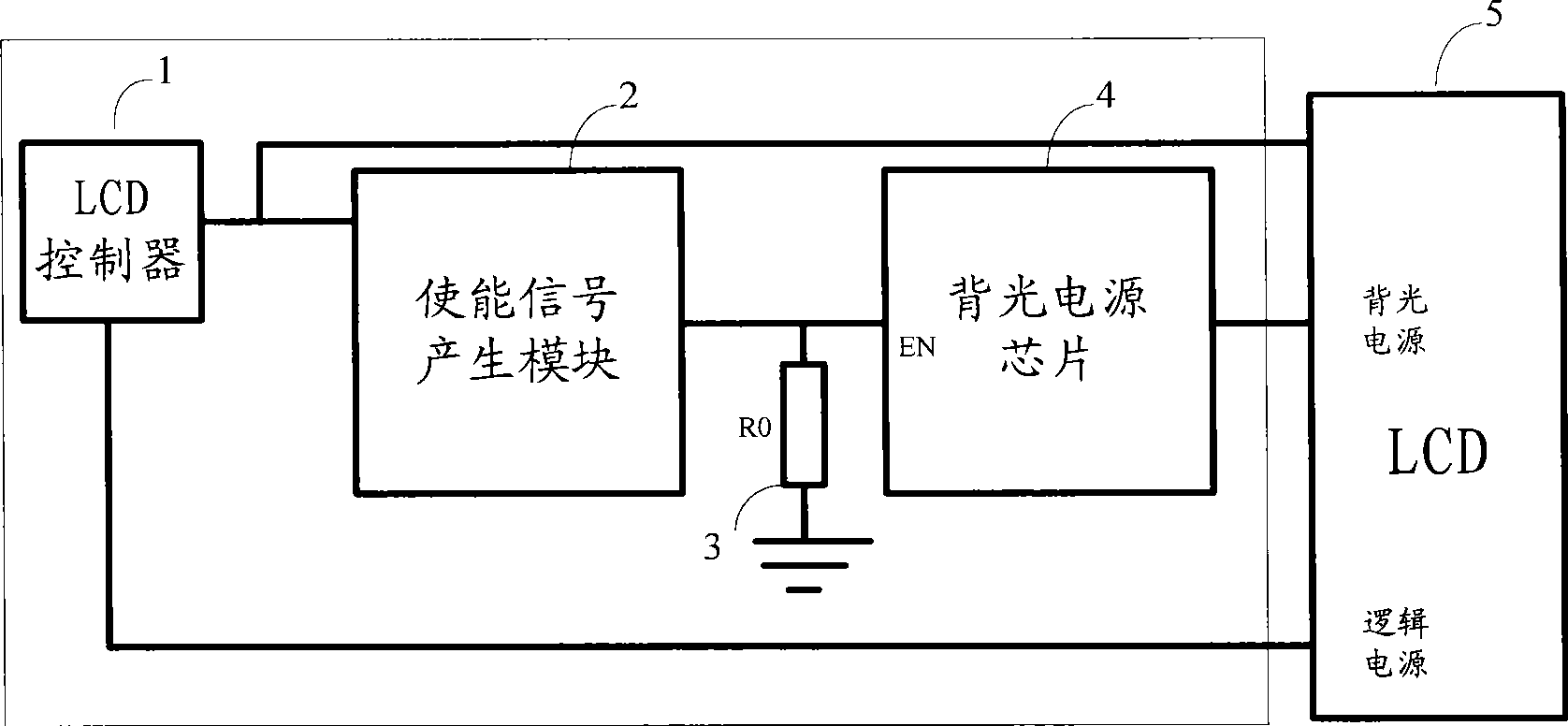
[0073] The difference between the third embodiment and the first embodiment is that the output terminal of the enabling signal generating module 2 is connected to the third input terminal of the enabling signal generating module 2 to form a feedback loop.

[0074] When the LCD 5 is turned on and powered on, the LCD controller 1 is started by the logic power supply. The LCD controller 1 outputs a control signal to the enable signal generating module 2 .

[0075] The enable signal generating module 2 sends the enable signal to the backlight power supply chip 4 after receiving the control signal output by the LCD controller 1 and the enable signal fed back by itself.

[0076] The backlight power supply chip 4 receives the enable signal, is enabled, and lights up the LCD 5 .

[0077] The pull-down resistor R0 3 is used to ensure that the backlight power supply chip 4 is disabled at the moment when the LCD 5 is powered on.

[0078] The control device according to the third embodi...

Embodiment 5

[0110] The difference between the fifth embodiment and the fourth embodiment is that the control device further includes a CPU controller 7 .

[0111] The power supply interface of the LCD controller 1 is connected to the controller power supply 6 . The output terminal of the LCD controller 1 is connected to the first input terminal of the enable signal generating module 2 and the control signal input terminal of the LCD 5 . The logic power supply of the LCD 5 is connected to the second input terminal of the enable signal generating module 2 . One output port of the CPU controller 7 is connected to the third input end of the enable signal generating module 2 . The output terminal of the enable signal generating module 2 is connected to the enable pin of the backlight power supply chip 4 . The output terminal of the backlight power supply chip 4 is connected to the backlight power supply of the LCD 5 . The pull-down resistor R03 is connected between the enable pin of the bac...


PUM


Abstract

The invention particularly discloses a control device for starting an LED power supply. A power interface of an LED controller is connected with a logic power supply of an LED, and the output end of the power interface is connected with the first input end which makes a signal to generate a module and the control signal input end of the LED; the output end which makes a signal to generate a module is connected with an enabling pin of a backlight power supply chip; the output end of the backlight power supply chip is connected with a backlight power supply of the LED; after the LED controller is started, a control signal is output to an enabling signal generating module and the LED; and the enabling signal generating module receives the control signal of the LED controller, and outputs the enabling signal to the backlight power supply chip, so that the backlight power supply chip can light the backlight source of the LED. The control device is adopted to effectively guarantee the starting of the backlight power supply of the LED on the logical power supply after electricity switching, and ensure correct order starting of the logic power supply of the LED and the backlight power supply.

Description

technical field [0001] The invention relates to the field of control, in particular to a control device for starting an LCD power supply. Background technique [0002] Liquid Crystal Display (LCD: Liquid Crystal Display) is to place liquid crystals between two parallel glasses. There are many vertical and horizontal small wires between the two glasses. The direction of the rod-shaped crystal molecules is controlled by electrifying or not. The light is refracted to create the picture. [0003] LCD generally needs two power supplies, including logic power supply and backlight power supply. Since the life of the LCD is generally limited by the life of the backlight, and most of the power consumption of the LCD is consumed by the backlight. Therefore, if the backlight is turned on frequently when it is not needed, it will not only affect the service life of the LCD as a whole, but also increase the power consumption of the LCD. Based on the above reasons, in order to ensure t...

Claims


Application Information

Patent Timeline
Patent Type & Authority Applications(China)
IPC IPC(8): G09G3/36
Inventor 周翔姚高尚杨栋
Owner SANY HEAVY IND CO LTD (CN)
Why Eureka
Try Eureka