
Hybrid stepping motor rotor

A stepping motor and hybrid technology, applied in the field of electromechanical, can solve the problems of small output torque, saturation of the magnetic circuit, and prone to local saturation points.

Active Publication Date: 2021-02-02
XIAN AEROSPACE PROPULSION TESTING TECH RES INST
View PDF12 Cites 0 Cited by
  • Summary
  • Abstract
  • Description
  • Claims
  • Application Information

AI Technical Summary

Problems solved by technology

[0006]4. The magnetic circuit of the rotor yoke is required to be in an unsaturated state during design, otherwise it will not meet the basic requirements of stepping motor design;
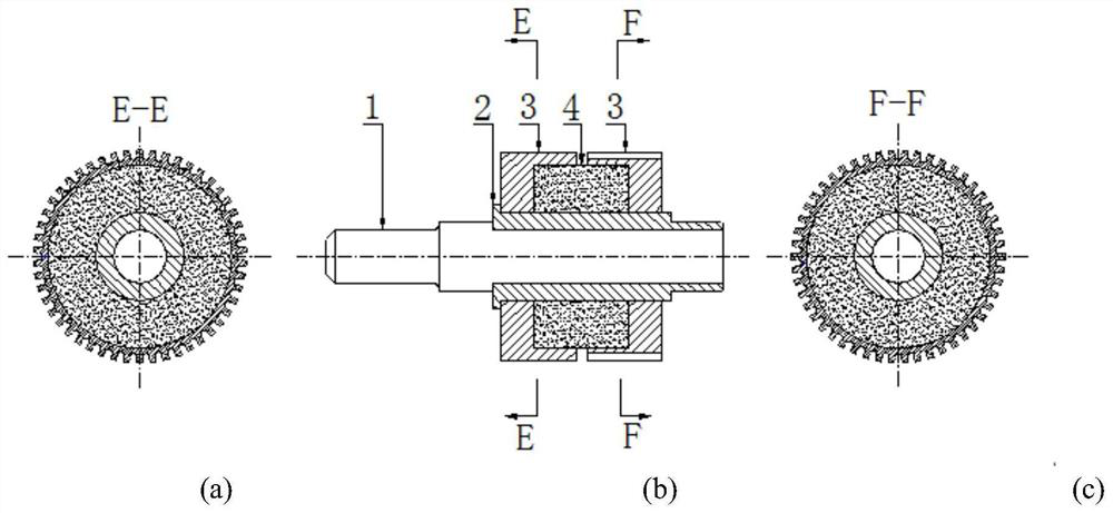
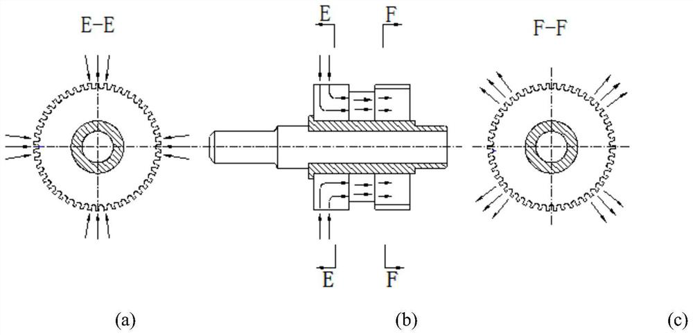
[0015](4)Figure 2 The local magnetic circuit of the yoke may be saturated: Figure 2 is prone to local magnetic circuit saturation due to small magnetic circuit (see Figure 5 shows the local saturation point), at this time, only the cross-sectional area of ​​the magnetic steel can be reduced to reduce the magnetic density B of the teeth of the yoke
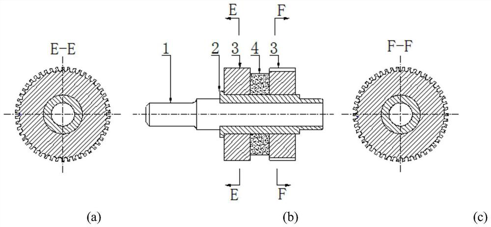
[0017]Figure 1, Figure 2 are conventional The hybrid stepper motor rotor structure can realize the normal operation of the hybrid stepper motor; Picture 1 will definitely not have a local saturation point of the yoke, but the output torque is relatively small; Figure 2 Increasing the length of the magnetic steel will increase the rotor flux, thereby increasing the output torque, but it is prone to local saturation points. If local saturation points are to be avoided, the ideas in the prior art It is to reduce the cross-sectional area of ​​the magnetic steel to reduce the magnetic density B of the teeth of the yoke, and use the finite element simulation software of the three-dimensional model for iterative verification

Method used


Image

  • Hybrid stepping motor rotor
  • Hybrid stepping motor rotor
  • Hybrid stepping motor rotor

Examples


Embodiment Construction

[0040] Embodiments of the present invention are described in detail below, and the embodiments are exemplary and intended to explain the present invention, but should not be construed as limiting the present invention.

[0041] This embodiment redesigns the path of the rotor magnetic circuit, proposes a new hybrid stepper motor rotor and its design method, improves the partial saturation of the yoke magnetic circuit, further increases the rotor magnetic flux Φ, and increases the output torque of the motor.

[0042] to further eliminate Figure 5 The local saturation point shown in this embodiment adopts a tapered magnetic steel structure to increase the cross-sectional area of ​​the local saturation point, so that under the same magnetic flux conditions, the local saturation phenomenon will no longer occur, the entire magnetic circuit is smooth, the magnetic resistance is reduced, and the magnetic resistance is improved. Motor output torque. Image 6 It is a new magnetic stee...


PUM


Abstract

The invention provides a hybrid stepping motor rotor, which comprises a rotor shaft, a magnetic isolation ring, a magnet yoke and magnetic steel, wherein the magnetic steel is embedded into the magnetyoke, the magnetic steel is of a bidirectional conical structure with the large outer diameter of the axial middle position and the small outer diameters of the two axial end positions, the taper angle of the conical structure is related to the outer diameter of a rotor, and taper angle iteration is carried out in a mode that the relation between the maximum magnetic flux density of a magnetic circuit and the saturation value of the magnetic flux density of a magnetic material is judged through electromagnetic simulation according to a preset initial taper angle so as to obtain the optimal taper angle. According to the invention, local saturation of a magnet yoke magnetic circuit can be improved, the rotor flux phi is further increased, and the output torque of the motor is increased.

Description

technical field [0001] The invention belongs to the field of electromechanical technology, in particular to a hybrid stepping motor rotor. Background technique [0002] Hybrid stepper motor rotor mainly has two typical magnetic circuit structures, see figure 1 and figure 2 As shown, their common characteristics mainly include the following points: [0003] 1. Parts characteristics: The rotor shaft carries torque output, so the metal material needs heat treatment to increase the hardness of the material, but the materials used also have magnetic properties; the magnetic isolation ring is mainly used to shield the magnetic flux leakage from the main magnetic circuit of the rotor to the rotor shaft; the yoke Use soft magnetic materials to reduce the reluctance of the magnetic circuit; the magnetic steel provides the magnetic source for the whole stepper motor; the parts and materials used in different rotor structures are all of the same grade, so as to compare the advantage...

Claims


Application Information

Patent Timeline
IPC IPC(8): H02K37/14H02K1/27H02K15/03G06F30/17G06F30/23
CPCH02K37/14H02K1/2706H02K15/03G06F30/17G06F30/23
Inventor 郗珂庆李敏哲杨凡胡博高俊丽胡昊苏倩郭炳岐
Owner XIAN AEROSPACE PROPULSION TESTING TECH RES INST
Learn More