
Compact conformal antenna for an implanted medical device telemetry system

a conformal, medical device technology, applied in electrotherapy, therapy, etc., can solve the problems of affecting rf performance, rf characteristics, rf specifications, etc., to enhance antenna efficiency, enhance communication, and enhance the effect of antenna efficiency

Inactive Publication Date: 2006-06-08
MEDTRONIC INC
View PDF2 Cites 15 Cited by
  • Summary
  • Abstract
  • Description
  • Claims
  • Application Information

AI Technical Summary

Benefits of technology

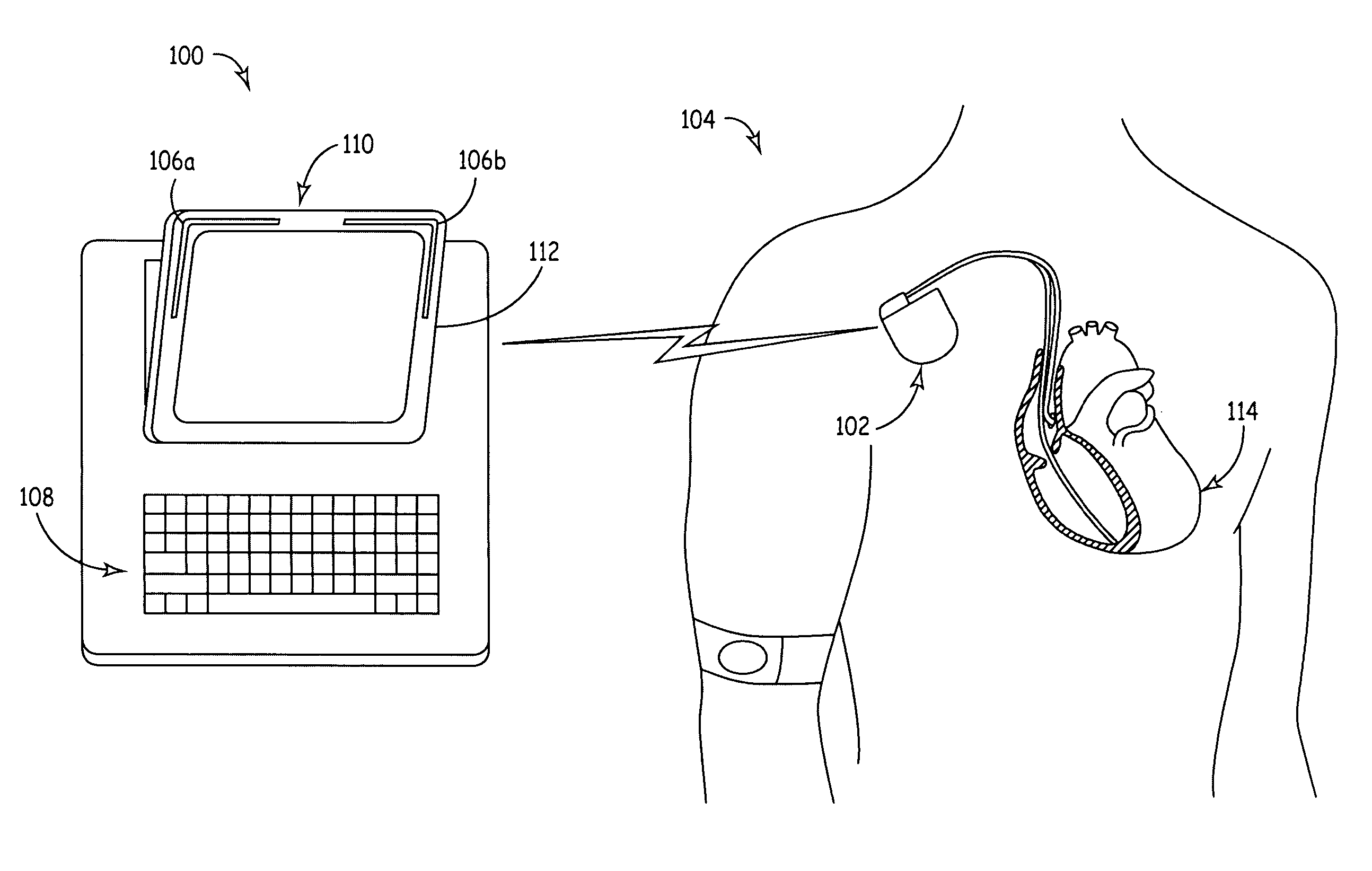
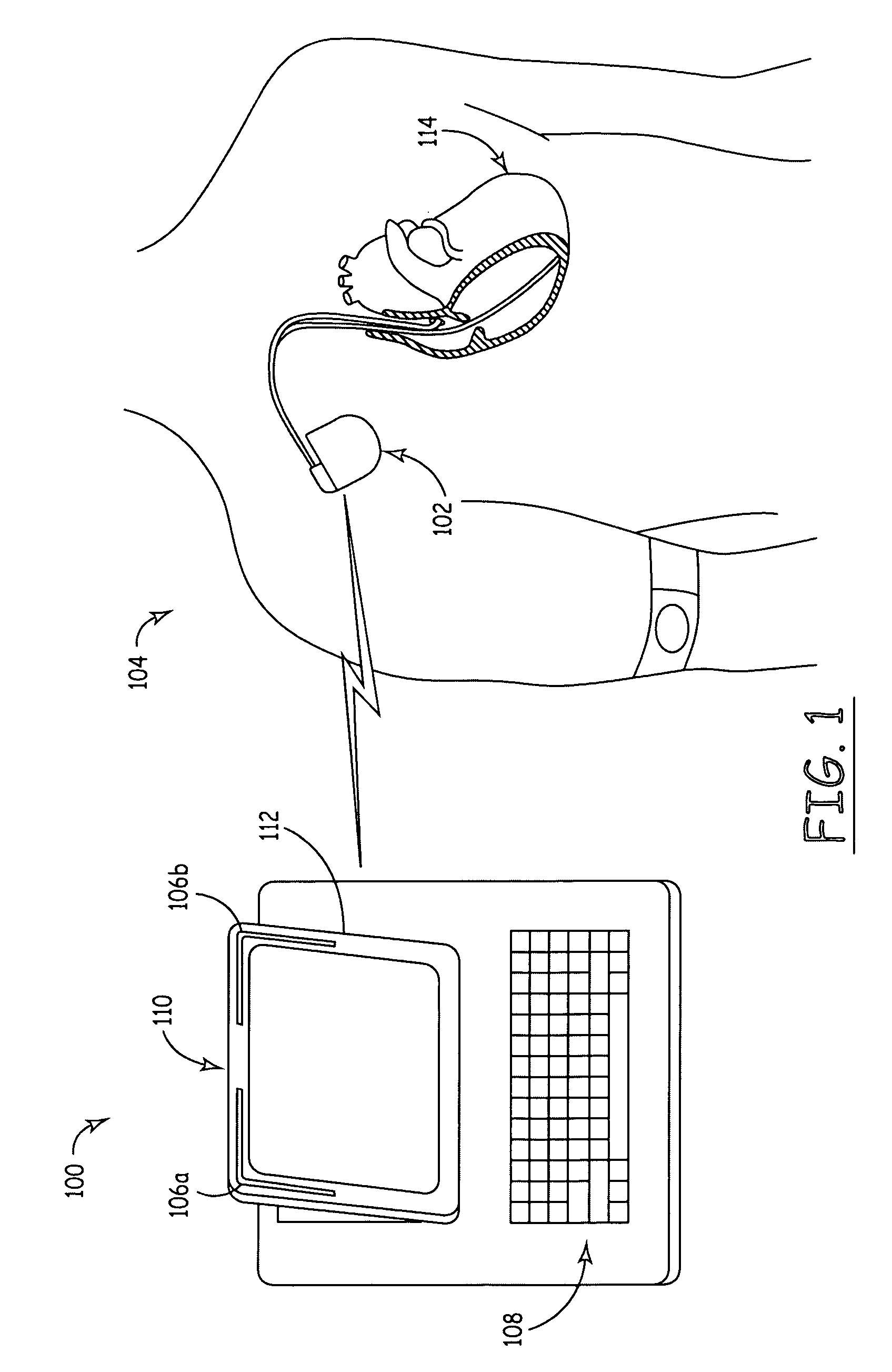
[0005] An antenna arrangement configured in accordance with an embodiment of the invention is suitable for use with far-field IMD telemetry equipment. The antenna arrangement is compact in size and conformal such that it can be deployed within the limited physical volume and space of the IMD telemetry equipment. Further, the antenna arrangement is configured to enhance communication between the IMD and the external telemetry component. The antenna arrangement is designed in response to the surrounding IMD telemetry equipment to enhance the antenna efficiency and, therefore, the far-field performance of the telemetry system.

Problems solved by technology

Various packaging requirements may create physical space limitations that can impact the RF characteristics, RF specifications, or RF performance of the telemetry component.

Method used


Image

  • Compact conformal antenna for an implanted medical device telemetry system
  • Compact conformal antenna for an implanted medical device telemetry system
  • Compact conformal antenna for an implanted medical device telemetry system

Examples


Embodiment Construction

[0017] The following detailed description is merely illustrative in nature and is not intended to limit the invention or the application and uses of the invention. Furthermore, there is no intention to be bound by any expressed or implied theory presented in the preceding technical field, background, brief summary or the following detailed description.

[0018] The invention may be described herein in terms of functional and / or logical block components and various processing steps. It should be appreciated that such block components may be realized by any number of hardware, software, and / or firmware components configured to perform the specified functions. For example, an embodiment of the invention may employ various integrated circuit components, e.g., memory elements, digital signal processing elements, logic elements, look-up tables, or the like, which may carry out a variety of functions under the control of one or more microprocessors or other control devices. In addition, thos...


PUM


Abstract

A telemetry component according to an embodiment of the invention, such as a programmer or a monitor for an implantable medical device (“IMD”), includes at least one radio frequency (“RF”) antenna that is configured to accommodate far-field telemetry between the telemetry component and the IMD. The RF antenna is shaped, sized, positioned, and otherwise configured to account for surface current cancellation caused by induced surface current on an electrically conductive surface of the telemetry component.

Description

TECHNICAL FIELD [0001] The present invention relates generally to wireless communication between an implanted medical device (“IMD”) and an external telemetry system, such as a programmer or monitor. More particularly, the invention relates to antennas for use with the external telemetry system. BACKGROUND [0002] An IMD and an external telemetry component, such as an IMD programmer or monitor, exchange information via wireless communication techniques. For example, the telemetry component typically transmits commands to the IMD using radio frequency (“RF”) data transmission methodologies. In addition, the IMD may transmit stored data or sensed physiological parameters to the external telemetry component. Traditional external telemetry components employ near-field RF data communication techniques that facilitate communication between the IMD and a telemetry head (attached to the telemetry component) that must be placed in close proximity to the IMD to establish the data communication...

Claims


Application Information

Patent Timeline
IPC IPC(8): A61N1/08
CPCA61N1/37229
Inventor NGHIEM, DAVIDFRANCIS, JOSHUA K.SIMONETTE, PAUL T.DUBLIN, GARRY L.SAZENSKI, RANDY R.HAUBRICH, GREGORY J.AARONS, TIMOTHY C.DENZENE, QUENTIN S.TWETAN, LEN D.
Owner MEDTRONIC INC
Learn More