Guillotine cutter

a technology of guillotine cutter and guillotine plate, which is applied in the direction of metal working apparatus, etc., can solve the problems of complicacy, defective products including such book binding errors are progressed to subsequent processes, and it is difficult to overcome the problem, so as to achieve simple and low-cost configuration, the effect of detecting the missing pag

Inactive Publication Date: 2006-06-15
HORIZON INTERNATIONAL INC
View PDF9 Cites 27 Cited by
  • Summary
  • Abstract
  • Description
  • Claims
  • Application Information

AI Technical Summary

Benefits of technology

[0007] Therefore, it is an object of the present invention to enable detection of page missing and page redundancy during book binding processes with a simple and low-cost configuration, without providing a weight detecting device.

Problems solved by technology

However, it has been impossible to overcome the problem that defective products including such book binding errors are progressed to subsequent processes due to the detection accuracies of such detectors and monitoring devices and operators' inefficient handling.
However, the aforementioned configuration has required a wide space for installing the weight detecting device, thereby causing the problem of complicacy and high cost of the entire book binding system.

Method used


Image

  • Guillotine cutter
  • Guillotine cutter
  • Guillotine cutter

Examples


Embodiment Construction

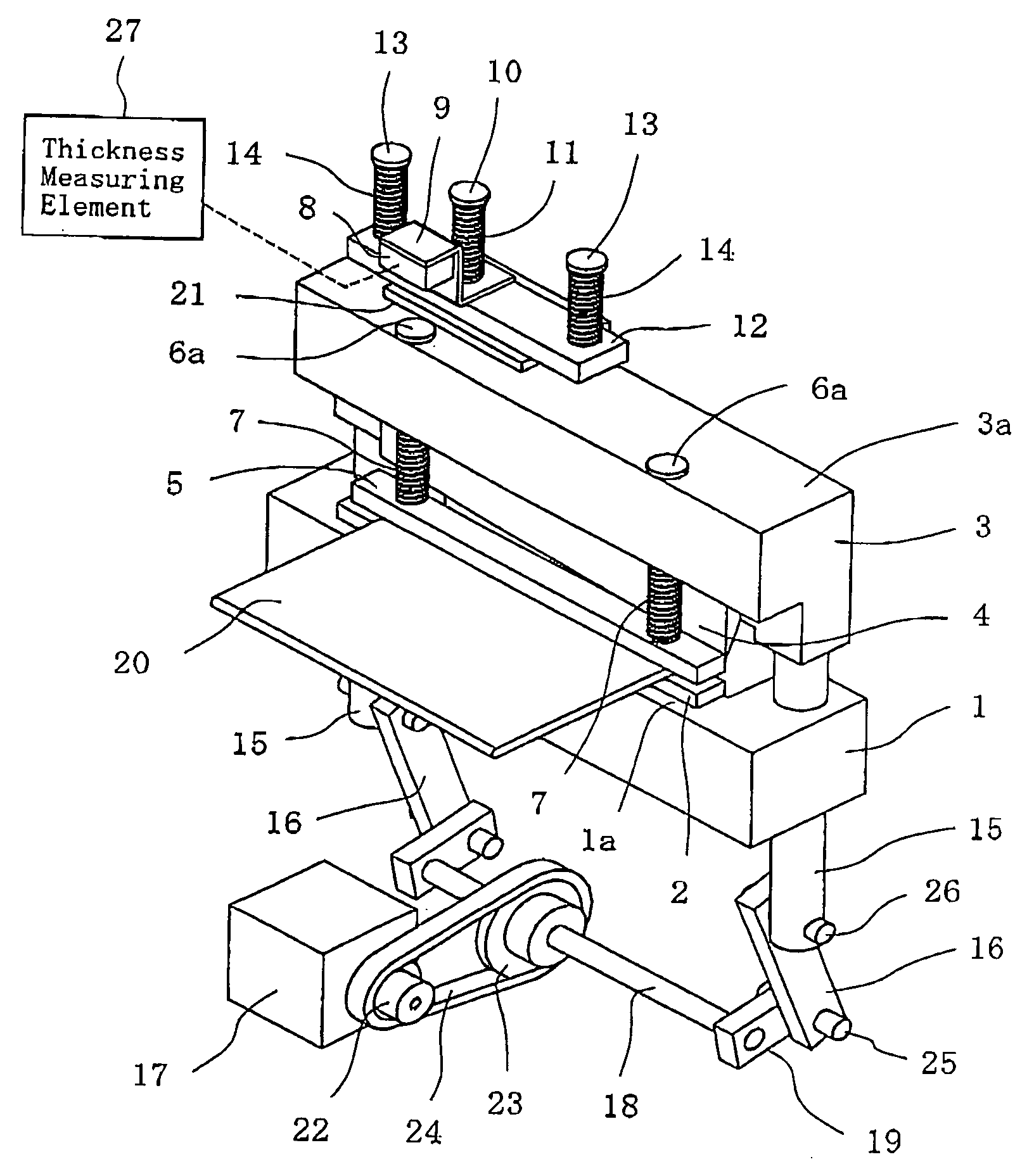
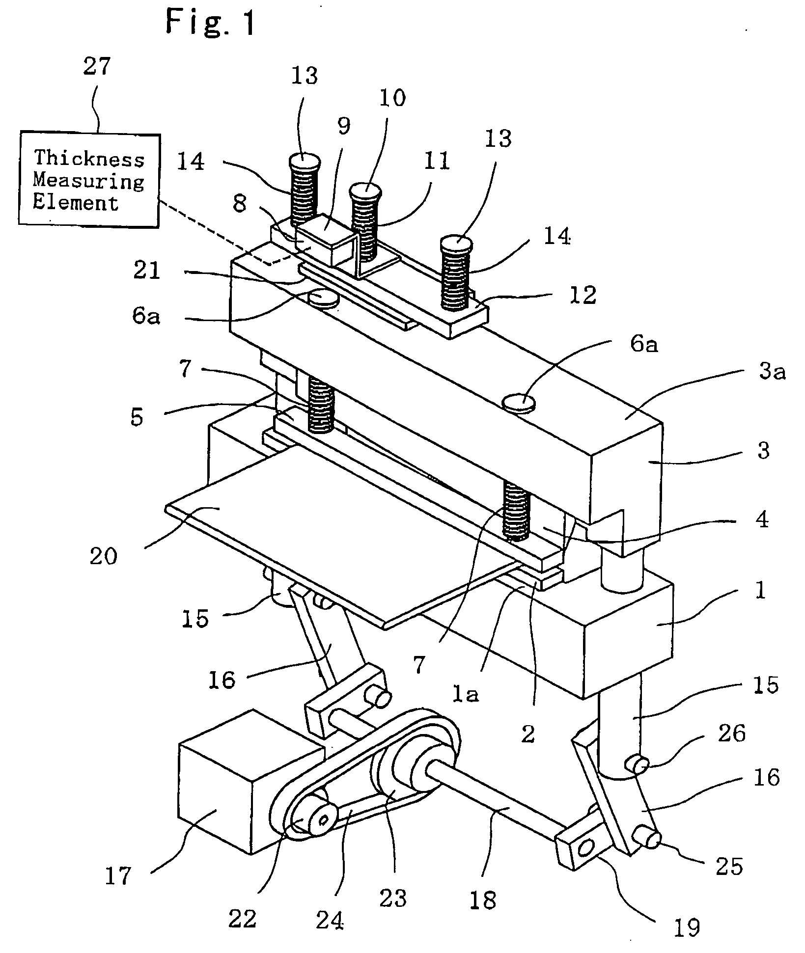
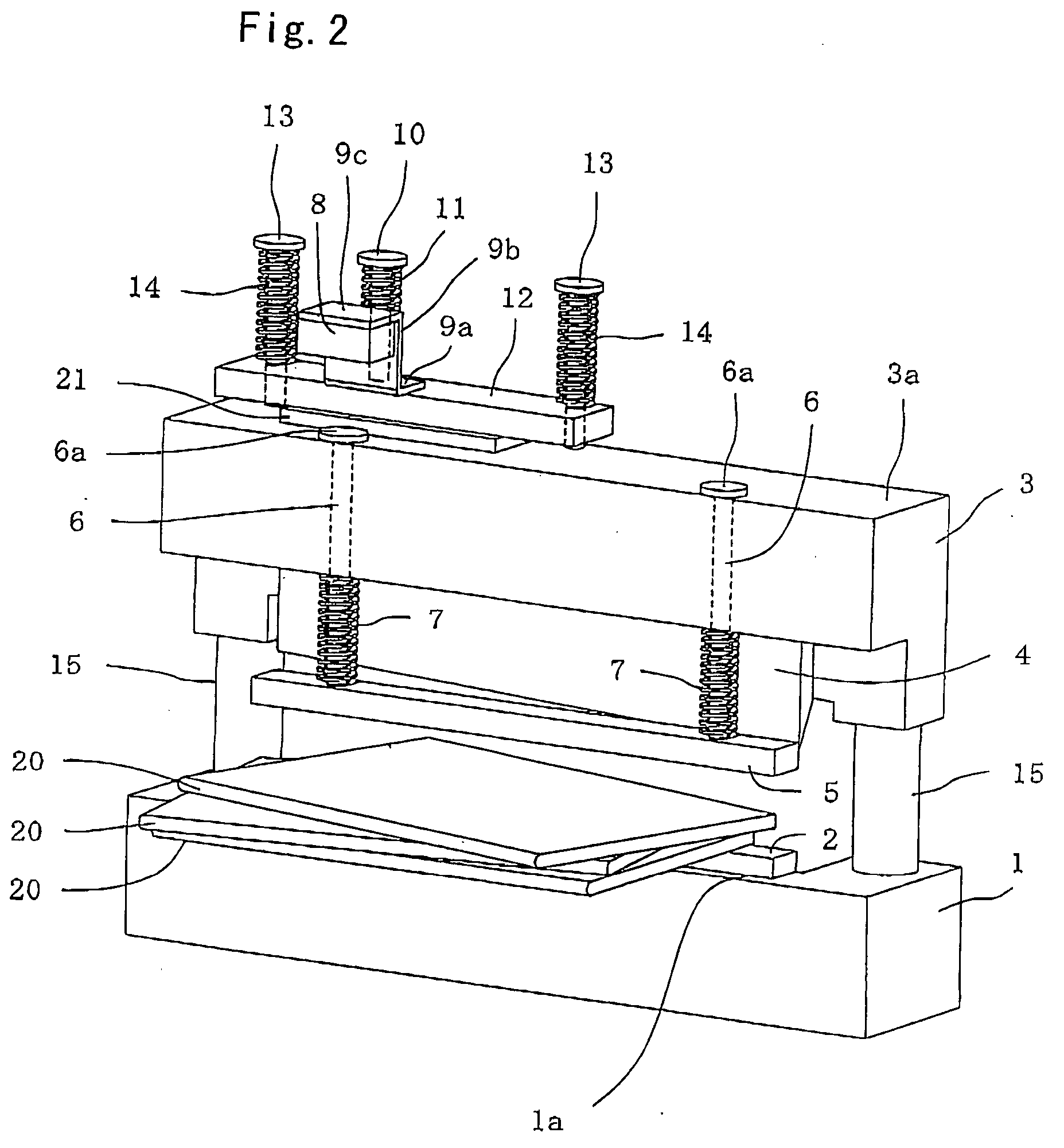
[0017] Hereinafter, a preferred embodiment of tie present invention will be described with reference to the attached drawings. FIG. 1 is a perspective view illustrating the configuration of main part of a guillotine cutter according to a first embodiment of the present invention, FIG. 2 is an enlarged view illustrating the configuration of a portion for detecting the thickness of a batch of paper in the guillotine cutter illustrated in FIG. 1. Referring to FIG. 1, the guillotine cutter according to the present invention includes a frame 1 including an elongated rectangular-shaped flat supporting surface la and a lower guillotine cutter blade 2 mounted on the supporting surface la of the frame 1. The lower guillotine cutter blade 2 is constituted by a blade portion extending along one side edge of the supporting surface 1a and a flat plate portion continuous with the blade portion for placing a portion of a batch of paper 20 thereon.

[0018] The guillotine cutter further includes a gu...


PUM

PropertyMeasurementUnit
elastic biasing forceaaaaaaaaaa
distanceaaaaaaaaaa
thicknessaaaaaaaaaa

Abstract

A lower guillotine cutter blade (2) is mounted to a frame (1). A guillotine cutter-blade holder (3) holds an upper guillotine cutter blade (4) and vertically reciprocates with respect to the lower guillotine cutter blade (2). Rods (6) are vertically slidably mounted to the guillotine cutter-blade holder (3). A pressing plate (5) is secured to the lower ends of the rods (6). Springs (7) are fitted around the rods (6) between the guillotine cutter-blade holder (3) and the pressing plate (5) for downwardly elastically biasing the rods (6) so that the heads (6a) of the rods are kept abutted against the guillotine cutter-blade holder (3). In a cutting operation, after the pressing plate (5) is brought into abutment with a batch of paper (20), the guillotine cutter-blade holder (3) is further downwardly moved, thereby causing the lower and upper guillotine cutter blades (2 and 4) to cut the batch of paper (20) and also causing the heads (6a) to upwardly protrude from the guillotine cutter-blade holder (3). At this time, a sensor (8) mounted to the guillotine cutter-blade holder (3) detects the distance to the heads (6a). A thickness measuring element (27) determines the thickness of the batch of paper (2) on the basis of the detection signal.

Description

TECHNICAL FIELD [0001] The present invention relates to a guillotine cutter provided with a thickness measuring device for measurement of the thickness of a batch of paper to be cut. BACKGROUND ART [0002] Some conventional book binding apparatuses are configured to accumulate, in order, predetermined number of paper sheets or quires such as printing paper sheets to form a batch of paper, fold the batch of paper into halves, bind the folded portion to form a book, and trim the fore edge of the book, or the fore, top, and bottom edges. [0003] Such book binding apparatuses include various types of detectors and monitoring devices in order to prevent the occurrence of book binding errors such as page missing which is a dropout of a portion of paper sheets constituting a book and page redundancy which is redundancy of paper sheets. [0004] However, it has been impossible to overcome the problem that defective products including such book binding errors are progressed to subsequent process...

Claims


Application Information

Patent Timeline
Patent Type & Authority Applications(United States)
IPC IPC(8): B26D1/00
CPCB26D5/00B26D7/025B26D7/22Y10T83/178Y10T83/541Y10T83/7513Y10T83/758Y10T83/851Y10T83/9454
Inventor FUJITA, KAZUHISAOUCHIYAMA, KOKATAYAMA, EIJI
Owner HORIZON INTERNATIONAL INC
Why Eureka
Try Eureka