Solar energy system

a solar energy and system technology, applied in solar heat devices, climate sustainability, lighting and heating equipment, etc., can solve the problems of comparatively rare, known and generally unsightly additions to the roofs of many buildings

Inactive Publication Date: 2006-06-15
PANEL IP
View PDF0 Cites 22 Cited by
  • Summary
  • Abstract
  • Description
  • Claims
  • Application Information

AI Technical Summary

Problems solved by technology

It has long been known to provide solar collectors on the roofs of buildings for the purpose of heating hot water and such collectors are well known, and generally unsightly, additions to the roofs of many buildings.
Although such space heating systems are known, for various reasons they have not found widespread commercial acceptance and are therefore comparatively rare.

Method used


Image

  • Solar energy system
  • Solar energy system
  • Solar energy system

Examples


Embodiment Construction

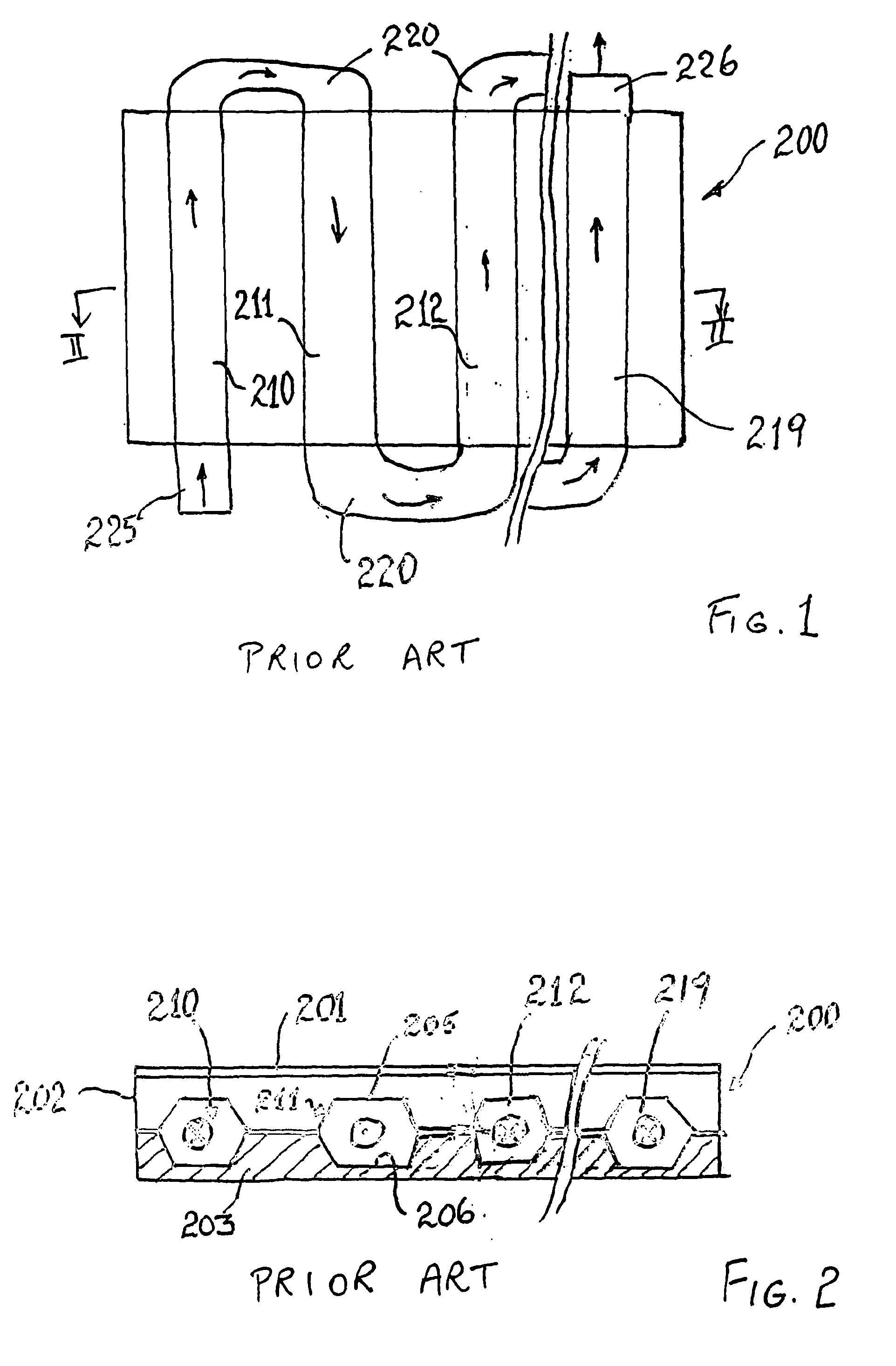
[0032] As illustrated in FIGS. 1 and 2, conventional thermal solar absorber for heating hot air take the form of a collector box 200 having a glass top 201, side walls 202 and an insulated base 203. Located within the box 200 are two opposed sheets 205, 206 generally formed from profiled roofing material. The opposed profiles define a number of parallel ducts 210, 211, 212, . . . 219 which are joined end to end by U-shaped insulated manifolds 220 located exterior of the collector box 200. As indicated by arrows in FIG. 1, a serpentine flow path is created with air flowing through each of the ducts 210, 211, 212, . . . 219 in sequence between an inlet 225 and outlet 226.

[0033] Located between the glass top 201 and the upper sheet 205 is a stagnant air space which insulates the ducts 210, 219. The upper sheet 205 forms the heat absorbing surface.

[0034] This prior art arrangement suffers from various efficiency disadvantages including that the area of the actual ducts (210, 211, 212,...


PUM


Abstract

The present invention discloses a solar array cell (15) able to be used both thermally and photovoltaically, together with an array (3) formed from a plurality of the cells (15). A solar energy system for a building which incorporates the array (3) is also disclosed. Each cell (15) is formed from an air duct (16) of parallelogram cross-sectional shape which makes for easy sealing between ducts and a reliable water shedding arrangement for the cells of the array. An air/liquid heat exchanger (35) for a solar hot water supply is also disclosed.

Description

FIELD OF THE INVENTION [0001] The present invention relates to a solar energy system and, in particular, to a solar energy system for use in buildings which enables hot air to be generated for space heating, with the optional addition of either heat to be generated for hot water heating, and / or electricity to be generated from photovoltaic cells, or both. BACKGROUND ART [0002] It has long been known to provide solar collectors on the roofs of buildings for the purpose of heating hot water and such collectors are well known, and generally unsightly, additions to the roofs of many buildings. This is particularly the case in Australia where solar radiation levels are relatively high. Similarly, it is also well known to provide photovoltaic cells for the generation of electricity from solar radiation and such cells are in widespread use, particularly in rural and outback Australia in locations remote from power generation stations. In particular, in recent years such installations have ...

Claims


Application Information

Patent Timeline
Patent Type & Authority Applications(United States)
IPC IPC(8): F25B29/00E04D13/18F24D3/08F24D11/00F24J2/04F24J2/46F24S10/70F24S10/75F24S23/74F24S90/00F28D20/02
CPCF24D11/007F24J2/045F24J2/0477F24J2/24F24J2/4647F24J2002/0092F28D20/02Y02B10/12Y02B10/20Y02E10/44Y02E60/145Y02E70/30F24S80/30F24S20/67F24S2020/17F24S10/20F24S10/70Y02B10/10Y02E60/14
Inventor CURTIS, PAUL F.CURTIS, ROBERT A.DELANEY, ROSA W.
Owner PANEL IP
Why Eureka
Try Eureka