Steerable drill bit arrangement

Active Publication Date: 2006-06-15
WEATHERFORD TECH HLDG LLC
View PDF7 Cites 0 Cited by
  • Summary
  • Abstract
  • Description
  • Claims
  • Application Information

AI Technical Summary

Benefits of technology

[0022] Furthermore, it is a recognised feature of drill bits that they produce vibrational excitation in the drill string, in both longitudinal and lateral directions. This vibration can be damaging to drilling equipment and the borehole surface. It is another advantage of the present invention that the non-rotating stabiliser can provide some control over this bit-induced vibration.
that the non-rotating stabiliser can provide some control over this bit-induced vibration.

Problems solved by technology

It is necessary to stabilise such a drill string, i.e. during drilling (when the drill string rotates) the gap between the drill string and the borehole wall allows the drill string to move transversely relative to the borehole, possibly causing directional errors in the borehole, damage to the drill string, and / or lack of uniformity in the cross-section of the borehole.
Such arrangements have the disadvantage that the non-rotating drill string incurs greater frictional resistance to movement along the borehole, which limits the horizontal reach of the system.
A disadvantage of the “push the bit” systems, however, is that the drill bit is designed to work most efficiently when it is urged longitudinally against the earth or rock, and “push the bit” systems force the drill bit to move transversely, so that a transverse cutting action is required in addition to the longitudinal cutting action.
The result is that the borehole wall becomes roughened and / or striated, which can affect the drilling operation by impairing the passage of the stabilisers, and can also detrimentally affect the operation of downhole measuring tools which are required to contact the borehole wall.
The incorporation of a stabiliser has its own disadvantage, however, as the channels cut into the stabiliser to allow the passage of mud cause the stabiliser to dig into the borehole wall when it is subjected to a transverse (steering) force, i.e. the stabiliser acts to “ream” the borehole wall, reducing the steering moment which is applied to the drill bit and so reducing the degree of curvature of the borehole.

Method used


Image

  • Steerable drill bit arrangement
  • Steerable drill bit arrangement

Examples


Embodiment Construction

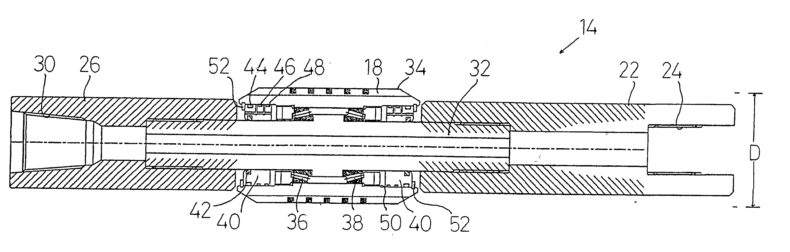
[0026] As shown in FIG. 1, the steerable drill bit arrangement 10 comprises a steering component 12 and a stabiliser 14. The steering component 12 and the stabiliser 14 are located in the drill string 16 adjacent the drill bit 20, with the stabiliser 14 being located between the steering component 12 and the drill bit 20. The steering component 12 serves to decentralise the drill string 16 within the borehole (not shown), so that the drill bit 20 is forced to deviate from a linear path. For example, if the steering component is used to force the drill string 16 downwardly in the orientation shown, then the drill bit 20 will be forced upwardly, the stabiliser 14 acting as the fulcrum.

[0027] In known fashion, the steering component 12, the stabiliser 14, and the pipe sections which make up the drill string 16, are hollow so as to allow the passage of mud to the drill bit 20. Also, the steering component 12 and the stabiliser 14 include channels 18 which permit the passage of mud from...


PUM


Abstract

This invention relates to a steerable drill bit arrangement, in particular for the use in drilling boreholes for oil and gas extraction. There is provided a steerable drill bit arrangement in which the drill bit (20) is connected to a drill string (16) including a steering component (12) and a stabiliser (14), the stabiliser (14) being located between the steering component (12) and the drill bit (20), the steering component (12) being adapted to move the drill string (16) transversely relative to a borehole in which it is located, the stabiliser (14) having an inner part (32) adapted to rotate with the drill string (16) and an outer part (34) adapted to engage the borehole wall, the outer part (34) being rotatable relative to the inner part so that the outer part (34) can remain substantially stationary as the remainder of the stabiliser (14) rotates with the drill string (16).

Description

FIELD OF THE INVENTION [0001] This invention relates to a steerable drill bit arrangement, in particular for the use in drilling boreholes for oil and gas extraction. DESCRIPTION OF THE PRIOR ART [0002] To extract oil and gas from underground reserves, it is necessary to drill a borehole into the reserve. Traditionally, the drilling rig would be located above the reserve (or the location of a suspected reserve) and the borehole drilled vertically (or substantially vertically) into the reserve. The reference to substantially vertically covers the typical situation in which the drill bit deviates from a linear path because of disconformities in the earth or rock through which the borehole is being drilled. [0003] Later, steerable drilling systems were developed which allowed the determination of a path for the drill bit to follow which was non-linear, i.e. it became possible to drill to a chosen depth and then to steer the drill bit along a curve until the drill was travelling at a de...

Claims


Application Information

Patent Timeline
IPC IPC(8): E21B17/10E21B7/06
CPCE21B7/062E21B17/1064
Inventor STROUD, DARYL RICHARD HENRYLARRONDE, MICHAEL L.
Owner WEATHERFORD TECH HLDG LLC
Why Eureka
Try Eureka