Method of manufacturing a piezoelectric/electrostrictive device

a piezoelectric and electro-electrostrictive technology, applied in piezoelectric/electrostrictive/magneto-strictive devices, piezoelectric/electrostriction/magneto-strictive machines, electrical apparatus, etc., can solve the problems of small operation amount of movable section b, /b>, and piezoelectric actuators, etc., to achieve excellent handling performance, high speed response, and high mechanical strength

Inactive Publication Date: 2005-03-24
NGK INSULATORS LTD
View PDF44 Cites 0 Cited by
  • Summary
  • Abstract
  • Description
  • Claims
  • Application Information

AI Technical Summary

Benefits of technology

[0010] The present invention has been made taking the foregoing problems into consideration, an object of which is to provide a piezoelectric / electrostrictive device and a method for producing the same which make it possible to obtain a displacement element that is scarcely affected by harmful vibration and capable of high speed response with high mechanical strength while being excellent in handling performance, shock resistance, and moisture resistance, making it possible to realize a long service life of a device, and improve the handling performance of the device and the attachment performance for parts to be attached to the movable section or the fixation performance of the device, so that the movable section may be greatly displaced at a relatively low voltage, and it is possible to achieve a high speed of the displacement action of the device, especially of the movable section (realization of a high resonance frequency), as well as a sensor element which makes it possible to accurately detect vibration of the movable section.

Problems solved by technology

However, the piezoelectric actuator described above involves such a problem that the amount of operation of the movable section 406 is small, because the displacement in the direction of expansion and contraction of the piezoelectric / electrostrictive material (i.e., in the in-plane direction of the plate-shaped member 400) is transmitted to the movable section 406 as it is.
That is, the mechanical strength is low, and the piezoelectric actuator is inferior in handling performance, shock resistance, and moisture resistance.
Further, the piezoelectric actuator itself is heavy, and its operation tends to be affected by harmful vibrations (for example, residual vibration and noise vibration during high speed operation).

Method used


Image

  • Method of manufacturing a piezoelectric/electrostrictive device
  • Method of manufacturing a piezoelectric/electrostrictive device
  • Method of manufacturing a piezoelectric/electrostrictive device

Examples


first embodiment

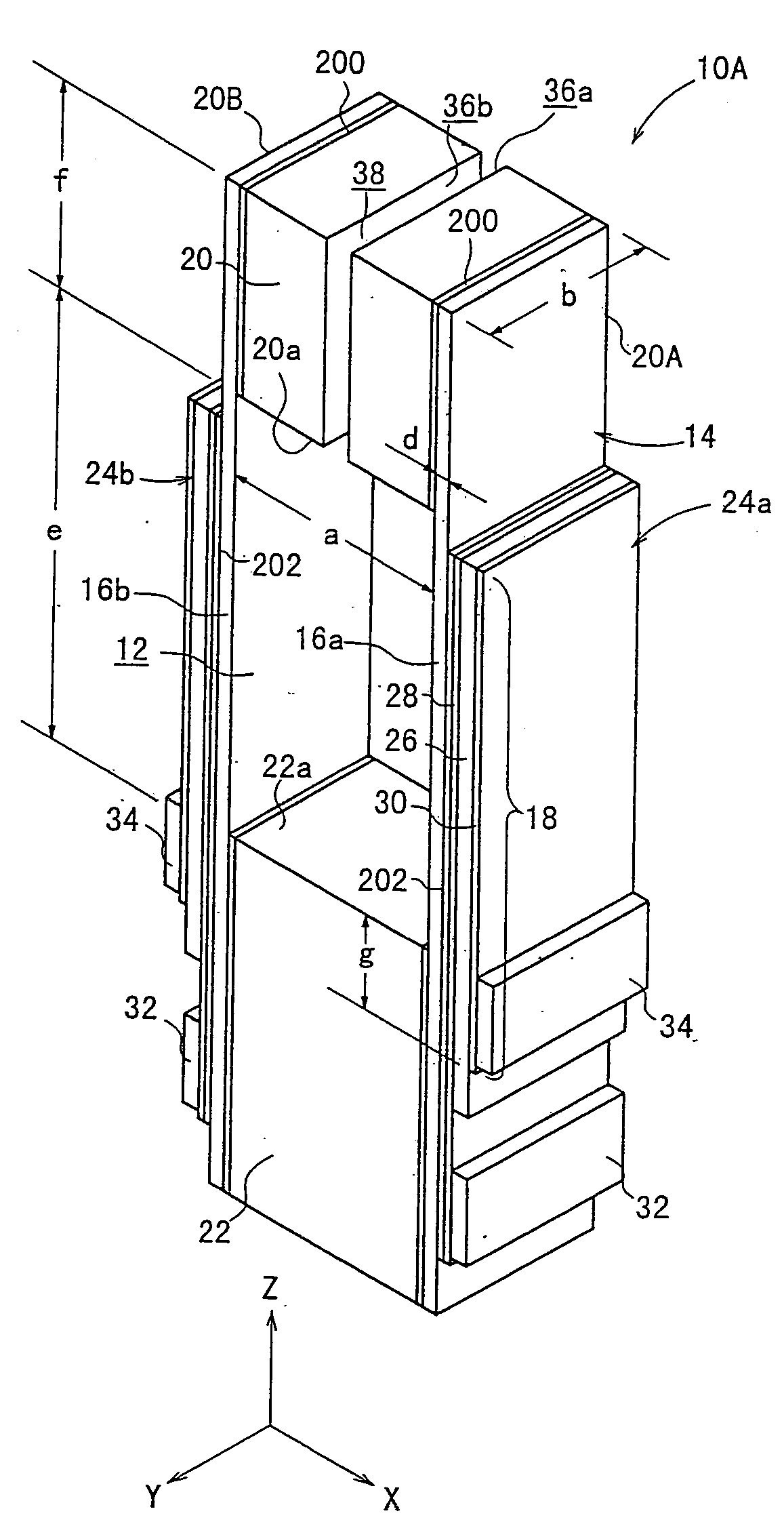
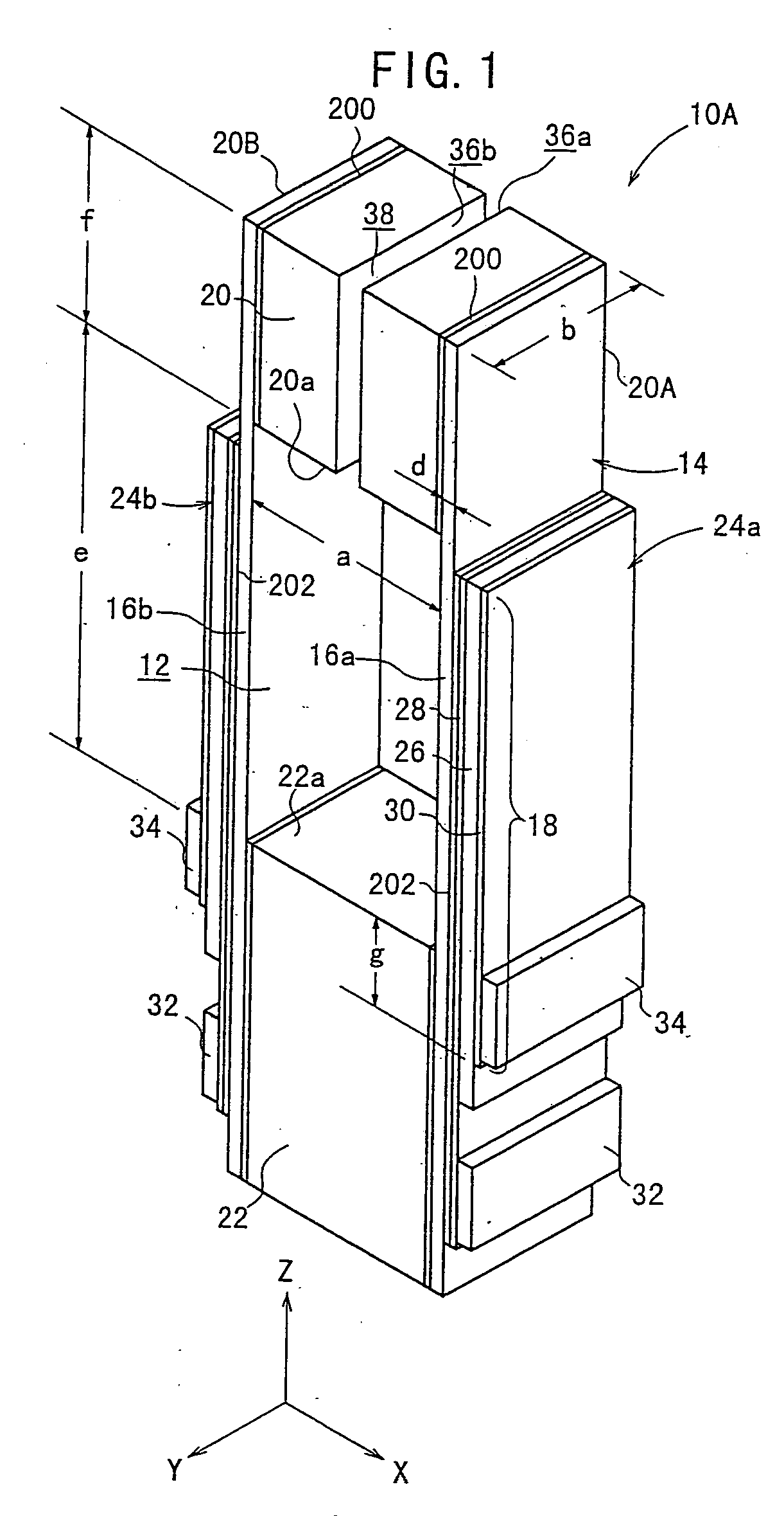
[0103] As shown in FIG. 1, the piezoelectric / electrostrictive device 10A has a substrate 14 which has a lengthy rectangular parallelepiped-shaped configuration as a whole and which has a hole 12 provided at an approximately central portion in the major axis direction thereof.

[0104] The substrate 14 comprises a pair of mutually opposing thin plate sections 16a, 16b, a movable section 20, and a fixation section 22 for supporting the pair of thin plate sections 16a, 16b and the movable section 20. Piezoelectric / electrostrictive elements 24a, 24b are formed at respective parts of at least the thin plate sections 16a, 16b respectively.

[0105] The substrate 14 may be constructed by using ceramics or metal for the entire substrate 14. Alternatively, the substrate 14 may have a hybrid structure obtained by combining those produced with ceramic and metal materials. Further, those adoptable for constructing the substrate 14 include, for example, a structure in which respective parts are bond...

seventh modified embodiment

[0112] As shown in FIG. 1, for example, a gap (air) 38 may be allowed to intervene between the end surfaces 36a, 36b. Alternatively, as in a piezoelectric / electrostrictive device 10Ag shown in FIG. 9 or as shown in FIG. 12, a member different from the constitutive member of the movable section 20, for example, a member 40 composed of, for example, resin or the like may be allowed to intervene between the end surfaces 36a, 36b.

[0113] In the piezoelectric / electrostrictive device 10A according to the first embodiment, the voltage is applied to the pair of electrodes 28, 30 via terminals (pads) 32, 34 of the respective electrodes 28, 30 formed on the both side surfaces (element formation surfaces) of the fixation section 22 respectively. The respective terminals 32, 34 are positioned as follows. That is, the terminal 32 corresponding to the first electrode 28 is formed at the position deviated toward the rearward end of the fixation section 22. The terminal 34 corresponding to the sec...

third modified embodiment

[0116] Alternatively, as in a piezoelectric / electrostrictive device 10Ac shown in FIG. 4, it is also preferable that the respective forward ends of the first electrode 28 and the piezoelectric / electrostrictive layer 26 are allowed to extend up to the side surface of the movable section 20, and the forward end of the second electrode 30 is located at an approximately central portion in the length direction (Z axis direction) of the thin plate section 16a, 16b.

[0117] In the embodiments described above, the piezoelectric / electrostrictive element 24a, 24b is constructed by the piezoelectric / electrostrictive layer 26 having the one-layered structure and the pair of electrodes 28, 30. Alternatively, it is also preferable that the piezoelectric / electrostrictive element 24a, 24b is constructed in a stacked form composed of a plurality of units each comprising the piezoelectric / electrostrictive layer 26 and the pair of electrodes 28, 30.


PUM

PropertyMeasurementUnit
distanceaaaaaaaaaa
distanceaaaaaaaaaa
widthaaaaaaaaaa

Abstract

A piezoelectric/electrostrictive (P/E) device includes a pair of mutually opposing metal thin plate sections, a movable section, and a fixation section for supporting the thin plate sections and the movable section. One or more piezoelectric/electrostrictive elements are arranged on at least one thin plate section of the pair of thin plate sections. Any one of the movable section and the fixation section has mutually opposing end surfaces, and a distance between the end surfaces is not less than the axial length of the movable section.

Description

CROSS REFERENCE TO RELATED APPLICATIONS [0001] This application is a continuation of U.S. application Ser. No. 10 / 281,373, filed Oct. 25, 2002, now allowed, which in turn is a division of U.S. application Ser. No. 09 / 676,209, filed Sep. 29, 2000, now U.S. Pat. No. 6,534,899, which claims the benefit under 35 USC §119(e) of U.S. Provisional Application Ser. No. 60 / 204,702, filed May 16, 2000, and is a continuation of U.S. application Ser. No. 09 / 524,042, filed Mar. 13, 2000, now U.S. Pat. No. 6,498,419, the entireties of which are incorporated herein by reference.FIELD OF THE INVENTION [0002] The present invention relates to a piezoelectric / electrostrictive device which is provided with a movable section to be operated on the basis of a displacement action of a piezoelectric / electrostrictive element, or a piezoelectric / electrostrictive device which is capable of detecting displacement of a movable section by the aid of a piezoelectric / electrostrictive element, and a method for produc...

Claims


Application Information

Patent Timeline
Patent Type & Authority Applications(United States)
IPC IPC(8): H01L41/083H01L41/09H01L41/273H01L41/39H02N2/04
CPCH01L41/0831H01L41/094H01L41/0946H01L41/0953H01L41/273Y10T29/49126Y10T29/42Y10T29/49789Y10T29/49128Y10T29/49798Y10T29/49005Y10T29/49574H10N30/501H10N30/2043H10N30/2044H10N30/2042H10N30/053
Inventor TAKEUCHI, YUKIHISASHIBATA, KAZUYOSHINAMERIKAWA, MASAHIKO
Owner NGK INSULATORS LTD
Why Eureka
Try Eureka