Voltage regulator using two operational amplifiers in current consumption

a voltage regulator and operational amplifier technology, applied in the direction of electric variable regulation, process and machine control, instruments, etc., can solve the problems of increasing chip area and incurring cost, and voltage regulators incur a great loss in electric current consumption, so as to reduce the chip area of voltage regulators, reduce the cost, and reduce the effect of electric current consumption

Inactive Publication Date: 2006-02-21
RICOH ELECTRONIC DEVICES CO LTD
View PDF13 Cites 29 Cited by
  • Summary
  • Abstract
  • Description
  • Claims
  • Application Information

AI Technical Summary

Benefits of technology

[0011]According to the voltage regulator of the present invention, the first operational amplifier operates in a normal operation mode so that the voltage regulator has good high-speed response, and the first operational amplifier stops operating and only the second operational amplifier operates in a low-electric-current consumption operation mode so that the voltage regulator operates with low electric current consumption. Thereby, the response of the voltage regulator

Problems solved by technology

If a voltage regulator having high-speed response is employed in an apparatus, such as a cellular phone, that consumes a normal amount of electric current in an operating state and a reduced amount of electric current in a wait state such as in a sleep mode, the voltage regulator incurs a great los

Method used


Image

  • Voltage regulator using two operational amplifiers in current consumption
  • Voltage regulator using two operational amplifiers in current consumption
  • Voltage regulator using two operational amplifiers in current consumption

Examples


first embodiment

[0021][First Embodiment]

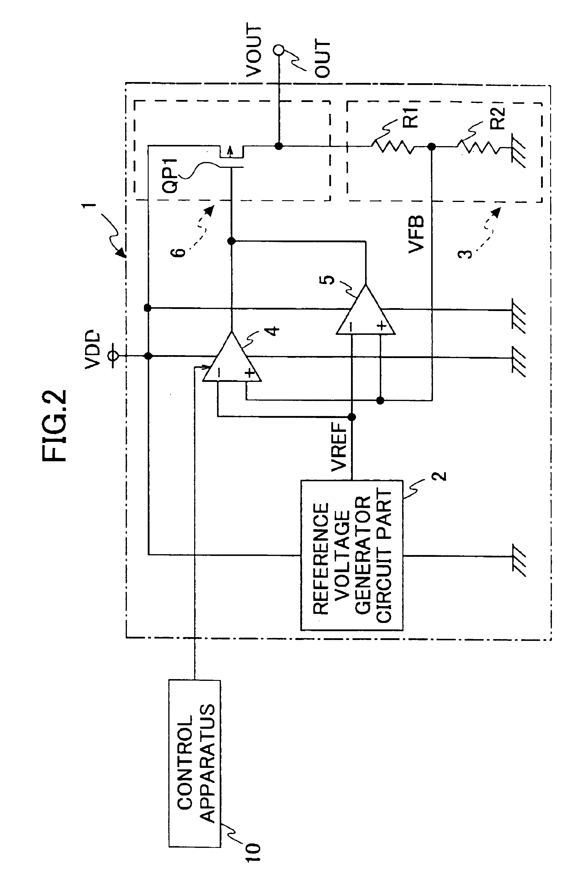
[0022]FIG. 2 is a schematic diagram showing a voltage regulator 1 according to a first embodiment of the present invention.

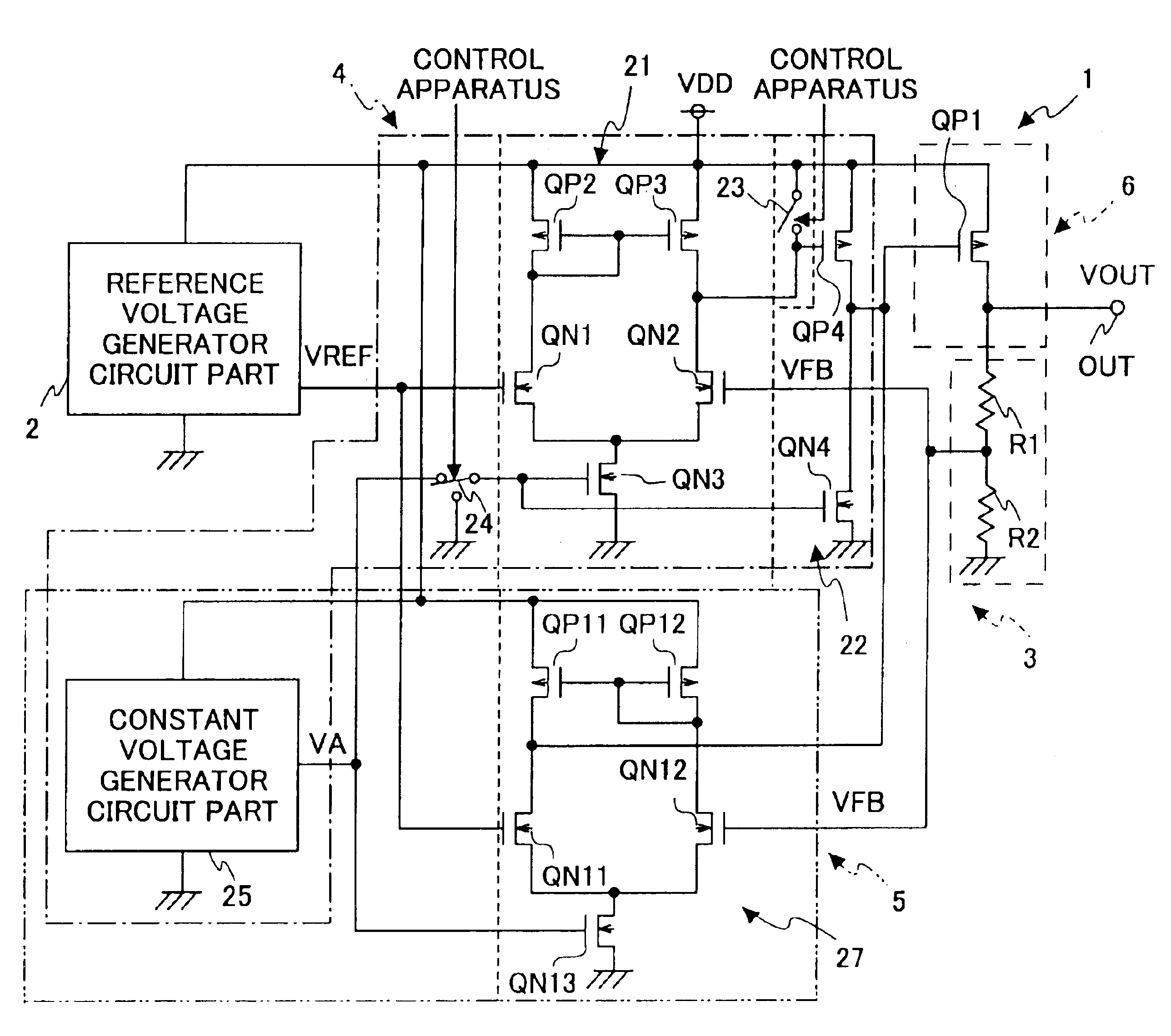
[0023]In FIG. 2, the voltage regulator 1 includes a reference voltage generator circuit part 2, a detection circuit part 3, a first operational amplifier 4, and a second operational amplifier 5. The reference voltage generator circuit part 2 generates and outputs a given reference voltage VREF. The detection circuit part 3 detects an output voltage VOUT, and generates and outputs a voltage VFB based on the detected output voltage VOUT. The first operational amplifier 4, which consumes a large amount of electric current but can operate at a high speed, compares the reference voltage VREF and the voltage VFB supplied from the detection circuit part 3 and outputs the comparison result. The second operational amplifier 5, whose electric current consumption is controlled (to a smaller amount than the first operational amplifier 4), compares th...

second embodiment

[0046][Second Embodiment]

[0047]In the above-described first embodiment, the second operational amplifier 5 operates constantly. On the other hand, in a second embodiment, the operation of the second operational amplifier 5 is stopped in the normal operation mode to further reduce electric current consumption.

[0048]FIG. 6 is a schematic diagram showing a voltage regulator la according to the second embodiment of the present invention. In FIG. 6, the same elements as those of FIG. 2 are referred to by the same numerals, and a description thereof will be omitted. The following description is given of a difference between the voltage regulator 1 of FIG. 2 and the voltage regulator 1a of FIG. 6.

[0049]The difference between the voltage regulator 1 of FIG. 2 and the voltage regulator 1a of FIG. 6 lies in that the second operational amplifier 5 of the first embodiment stops its operation so as not to consume electric current based on control signals supplied from the control apparatus 10 in...


PUM


Abstract

A voltage regulator, which generates and outputs a given voltage based on a preset reference voltage, includes: a detection circuit part detecting the output voltage and generating and outputting a voltage based on the detected voltage; first and second operational amplifiers each comparing the output voltage of said detection circuit part and the preset reference voltage and outputting a voltage representing a comparison result, the first operational amplifier being controlled based on control signals supplied externally and consuming a larger amount of electric current than the second operational amplifier; and an output circuit part comprising an output transistor outputting an electric current based on the output voltages of the first and second operational amplifiers.

Description

TECHNICAL FIELD[0001]The present invention relates to voltage regulators, and more particularly to a voltage regulator having the function of switching between a high-speed operation mode and a low-electric-current consumption operation mode.BACKGROUND ART[0002]Conventional voltage regulators are divided into two types: those having a circuit configuration consuming a large amount of electric current to increase power-supply rejection ratio (PSRR) and load transient response and those requiring no high-speed response and thus having a circuit configuration consuming a smaller amount of electric current. If a voltage regulator having high-speed response is employed in an apparatus, such as a cellular phone, that consumes a normal amount of electric current in an operating state and a reduced amount of electric current in a wait state such as in a sleep mode, the voltage regulator incurs a great loss in electric current consumption when the apparatus is in the wait state where no high...

Claims


Application Information

Patent Timeline
IPC IPC(8): G05F1/573G05F1/40G05F3/26G05F1/56G05F1/565G05F1/575
CPCG05F1/575G05F1/565
Inventor AGARI, HIDEKIYOSHII, KOHJI
Owner RICOH ELECTRONIC DEVICES CO LTD
Why Eureka
Try Eureka