Centrifugal separator with a control unit for speed control

a technology of centrifugal separator and control unit, which is applied in the direction of centrifuges, filtration separation, separation processes, etc., can solve the problems that the deposited particles (or sludge) are difficult to discharge from the separator, and achieve the effect of effective separation and transportation

Inactive Publication Date: 2018-04-17
ALFA LAVAL CORP AB
View PDF37 Cites 1 Cited by
  • Summary
  • Abstract
  • Description
  • Claims
  • Application Information

AI Technical Summary

Benefits of technology

[0003]An object of the present invention is to provide a centrifugal separator and a method for effectively separating and transporting the solid particles (sludge) from the liquid mixture and out of the rotor body.
[0007]Before the growing layer of sludge becomes a problem, the particle discharge phase of the present invention is initiated. During the particle discharge phase of the operating cycle, the rotor body is brought to rotate at a slower speed, whereby the centrifugal forces are decreased so that the screw conveyor may transport the sludge towards and out of the sludge outlet more easily. When essentially all of the sludge or at least a sufficient amount of sludge has been discharged from the separator, the rotor body is accelerated back to high speed rotation for the separation phase of the next operating cycle.
[0008]The differential speed between the screw conveyor and the rotor body may be activated exclusively during the particle discharge phase. However, according to an embodiment of the invention the control unit is adapted to control the drive arrangement to rotate the screw conveyor at a different speed than the rotor body during both the separation phase and the particle discharge phase. Through such a differential speed between the rotor body and the screw conveyor, some amount of the sludge may be discharged even during the separation phase. At any rate, through the upholding of the differential speed during the separation phase, the screw conveyor will distribute and work on the sludge to reduce some negative effects caused by the centrifugal forces compressing the sludge. One of those negative effects is that compressing the sludge will make it more difficult to discharge. Another negative effect is that the compressed sludge may be unevenly distributed in the rotor body, causing an unbalance with harmful vibrations of the centrifugal separator during operation.
[0015]According to yet another embodiment of the invention the rotor body is rotatably supported only at its one end through a rotor shaft, which is arranged so that the axis of rotation extends substantially vertically. This type of centrifugal separator is typically more light weight than for example a decanter centrifuge, which comprises a relatively heavy rotor body with a horizontal axis of rotation. The rotor body according to this embodiment is more suitable to accelerate back and forth between a separation phase and discharge phase. Such a separator will many times include a stack of truncated conical separation discs in the separation chamber, whereby the separation efficiency is improved. Furthermore, the inlet of such a separator would preferably include an inlet pipe, which extends into the rotor body at its one end, the liquid outlet for separated liquid including at least one outlet channel, which extends out of the rotor body at its one end, and the sludge outlet for separated solids situated at the opposite other end of the rotor body.

Problems solved by technology

At such a high rotational speed the deposited particles (or sludge) may be difficult to discharge from the separator, at least in a sufficient amount.

Method used


Image

  • Centrifugal separator with a control unit for speed control
  • Centrifugal separator with a control unit for speed control
  • Centrifugal separator with a control unit for speed control

Examples


Embodiment Construction

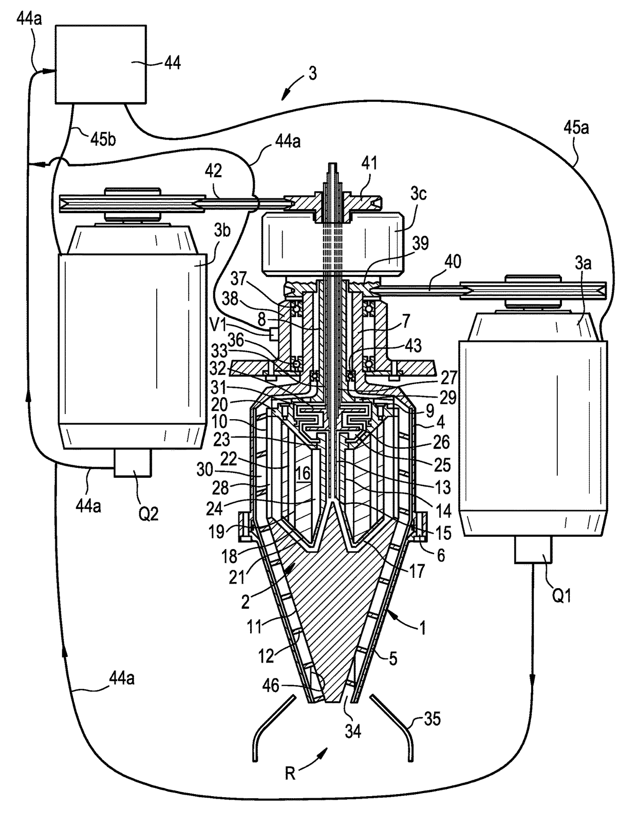
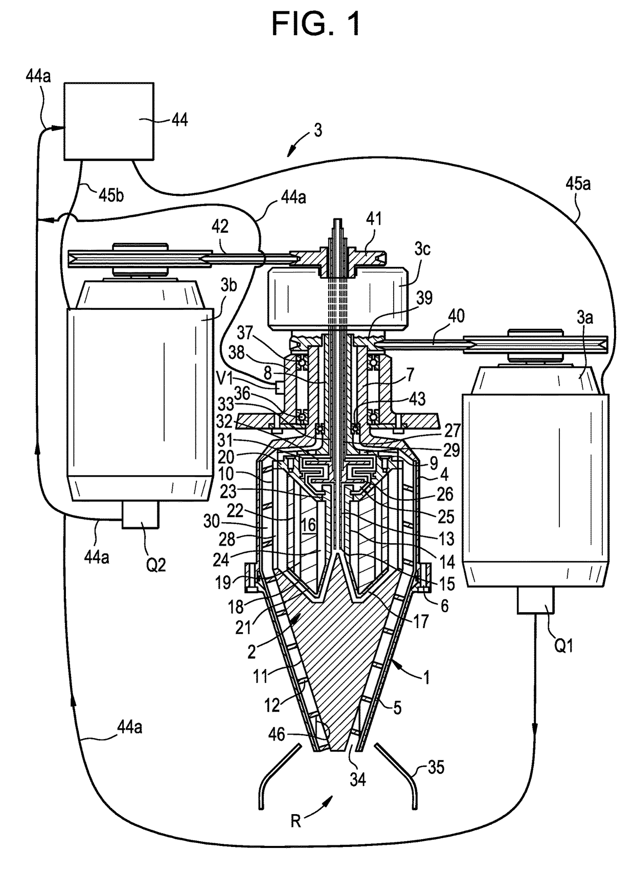
[0020]FIG. 1 discloses an embodiment of the invention. The centrifugal separator includes a rotor body 1, which is rotatable at a speed around a vertical rotational axis R, a screw conveyor 2 arranged in the rotor body 1 and rotatable around the same rotational axis R, however at a speed differing from the rotational speed of the rotor body 1. A drive arrangement 3 is adapted for rotation of the rotor body 1 and the screw conveyor 2 at their respective speeds. The drive arrangement 3 includes two electric motors 3a and 3b and a gear device 3c.

[0021]The rotor body 1 has a cylindrical upper rotor body portion 4 which is connected with a conical lower rotor body portion 5 by means of bolts 6. Alternative connection members can of course be used. The cylindrical rotor body portion 4 includes an extension axially upwards in the form of a hollow rotor shaft 7, which is connected to one of said electric motors 3a for rotating the rotor body 1 around the axis of rotation R.

[0022]A further ...


PUM

PropertyMeasurementUnit
densityaaaaaaaaaa
speedaaaaaaaaaa
rotational speedaaaaaaaaaa

Abstract

A centrifugal separator for separating solid particles from a liquid mixture includes a rotor body. The rotor body has a separation chamber with an inlet for the liquid mixture, one or more liquid outlets for a liquid separated from the liquid mixture, a sludge outlet for the separated solid particles, a screw conveyor adapted to rotate in the rotor body, at a speed differing from the rotational speed of the rotor body, for transporting the separated solid particles in the separation chamber towards and out of the sludge outlet, a drive arrangement adapted to rotate the rotor body and the screw conveyor at their respective speeds, and a control unit which is adapted to control the drive arrangement to rotate the rotor body at a first speed during a separation phase and at a second speed, which is lower than the first speed, during a particle discharge phase.

Description

FIELD OF THE INVENTION[0001]The present invention relates to a centrifugal separator for separating solid particles from a liquid mixture, the centrifugal separator comprising a rotor body which is rotatable around an axis of rotation, the rotor body having a separation chamber with an inlet for the liquid mixture, at least one liquid outlet for a separated liquid from the liquid mixture, a sludge outlet for the separated solid particles (also known as sludge), a screw conveyor arranged to rotate inside the rotor body around the axis of rotation for transporting the separated solid particles in the separation chamber towards and out of the sludge outlet, and a drive arrangement adapted to rotate the rotor body and the screw conveyor at their respective speeds. The present invention also relates to a method for separating solid particles from a liquid mixture.BACKGROUND OF THE INVENTION[0002]WO 2008 / 140378 discloses a centrifugal separator initially defined for purifying a fluid from...

Claims


Application Information

Patent Timeline
Patent Type & Authority Patents(United States)
IPC IPC(8): B04B1/20
CPCB04B1/2016B04B2001/2066B04B11/02B04B13/00
Inventor OLDEBACK, TOMASRIDDERSTRALE, ROLFGEIDING, ROBERTFONSER, PER
Owner ALFA LAVAL CORP AB
Why Eureka
Try Eureka