
Drilling speed improvement device capable of producing both hydraulic pulse and impact vibration

a technology of vibration and drill stem, which is applied in the direction of drilling drives, drilling pipes, drilling holes/well accessories, etc., can solve the problems of low drilling efficiency in deep formations, insufficient downhole hydraulic energy, and low drilling speed of deep wells, so as to improve the rock breaking efficiency of the drill bit and reduce the harm caused by the vibration of the drill stem

Active Publication Date: 2020-07-21
CHINA UNIV OF PETROLEUM (EAST CHINA)
View PDF11 Cites 1 Cited by
  • Summary
  • Abstract
  • Description
  • Claims
  • Application Information

AI Technical Summary

Benefits of technology

The patent text describes how the way the drill bit is impacted and the way drilling fluid is sprayed can be improved by the way the drill stem moves back and forth. This makes the drill bit more effective at breaking rock and reduces some of the damage caused by the movement of the drill stem.

Problems solved by technology

At present, low drilling efficiency in deep formations is a problem urgently to be solved.
There are various and complicated factors that may lead to low deep well drilling speed, among which insufficient downhole hydraulic energy and insufficient rock breaking efficiency of the drill bit, the vibration of the drill stem, and low energy utilization are major causes.
It will consume part of drilling fluid hydraulic energy to drive the pulse jet modulation device to work.
In insufficient deep well downhole hydraulic energy case, the consumption of part of drilling fluid hydraulic energy for this redistribution may influence the working effect of the drill in the deep well.

Method used


Image

  • Drilling speed improvement device capable of producing both hydraulic pulse and impact vibration

Examples


Embodiment Construction

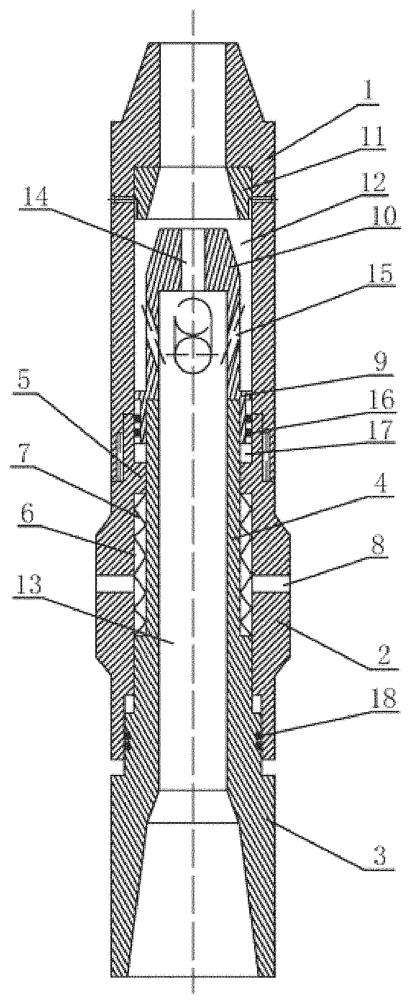
[0014]With reference to the accompanying drawing, a drilling speed improvement device capable of producing both hydraulic pulse and impact vibration is provided, comprising an upper joint 1, a drill body 2 and a lower joint 3, which are successively mounted in the axial direction. The upper joint 1 is connected to a drill stem. A lower end of the upper joint 1 is connected to an upper end of the drill body 2 by threads, and a lower end of the drill body 2 is connected to the lower joint 3. A pressure transfer rod 4 which is located in the center of the drill body 2 and coaxial to a fluid channel 13 to be described below is arranged at an upper end of the lower joint 3. The pressure transfer rod 4 is hollow, the inner diameter of which is greater than the outer diameter of the fluid channel 13. A bump 5 is arranged on the inner wall of the drill body 2. A spring chamber 6 is formed among the drill body 2, the bump 5, the pressure transfer rod 4 and the lower joint 3, and a spring 7 i...


PUM


Abstract

The present invention discloses a drilling speed improvement device capable of producing both hydraulic pulse and impact vibration. The device has a pressure transfer rod that is arranged at an upper end of a lower joint. A spring chamber is formed among a drill body, the pressure transfer rod and the lower joint. A spring is arranged in the spring chamber. A communicating hole is formed in the drill body. A piston is arranged at an upper end of the pressure transfer rod. A pressure bearing head is arranged at an upper end of the piston. A pressure bearing base is arranged on the inner side of an upper joint. Drill bit impact loads and drilling fluid pulse jets are modulated by the longitudinal vibration energy of a drill stem, the rock breaking efficiency of a drill bit is improved by both dynamic and static loads, and harm caused by vibration of the drill stem is reduced.

Description

CROSS-REFERENCE TO RELATED APPLICATIONS[0001]This application is a continuation of International Patent Application PCT / CN2018 / 102266, filed on Aug. 24, 2018, which claims the benefit of priority from Chinese Patent Application No. 201710975525.0, filed on Oct. 17, 2017. The content of the aforementioned application, including any intervening amendments thereto, is incorporated herein by reference.TECHNICAL FIELD[0002]The present invention discloses a drilling speed improvement device capable of producing both hydraulic pulse and impact vibration, belonging to the technical field of design of oil drills.BACKGROUND OF THE PRESENT INVENTION[0003]Fast drilling in deep hard formations is a key technique that restricts the development of deep or ultra-deep well drilling. At present, low drilling efficiency in deep formations is a problem urgently to be solved. Improving the rock breaking efficiency of the drill bit is the optimal way to improve the drilling speed. There are various and c...

Claims


Application Information

Patent Timeline
Patent Type & Authority Patents(United States)
IPC IPC(8): E21B31/113E21B6/02E21B7/24
CPCE21B7/24E21B6/02E21B31/113E21B17/076E21B21/00
Inventor LIAO, HUALINNIU, JILEIGUAN, ZHICHUANYANG, YANDONGSHI, YUCAILIU, YONGWANGXU, YUQIANG
Owner CHINA UNIV OF PETROLEUM (EAST CHINA)
Learn More