Distributing or Collecting Device

a technology of distributing device and collecting device, which is applied in the direction of component separation, gravity filter, loose filtering material filter, etc., can solve the problems of difficult to achieve, especially important, induction of fluid to be distributed, etc., and achieve the separation of desired fractions, improved separation of desired products, and better utilization of column filling material

Inactive Publication Date: 2006-06-15
FINPHIDE
View PDF10 Cites 13 Cited by
  • Summary
  • Abstract
  • Description
  • Claims
  • Application Information

AI Technical Summary

Benefits of technology

[0034] An advantage of the present invention is that the fluid is distributed and collected evenly across the whole cross-section area of the column, for example a chromatographic column, with minimum time delay, minimum time delay distribution and minimum mixing of the fluid fronts. The fluid is also distributed and / or collected with minimum turbulence throughout the cross-section of the column. The lack of time delay and minimum time delay distribution in the distributing and / or collecting of the fluid in a separation operation enhances the separation of the desired fractions. Another advantage of the present invention is that when the distributing and / or collecting device of the present invention is used in a column, for example a chromatographic column, the mixing volumes of the fluid fronts are at minimum. The small mixing volume of the fluid front enables a better utilisation of the column filling material. This means that a better separation of the desired products can be achieved with a smaller amount of column filling material. All this results further in lower investment costs.
[0035] Yet another advantage of the present invention is that the column filling material is kept apart from the distributing and / or collecting device and the column filling material does not clog the distributing and / or collecting devices. Another advantage of the distributing device and / or collecting device of the present invention is that they can advantageously be operated with low pressure drop. One of the advantages of the present invention is also that the use of the distributing and / or collecting device causes less dilution and the operating of a plant using either one or both of these devices is improved. This results also in small energy consumption e.g. because of lower concentrations are demanded. The devices of the present invention are also easily cleaned and it is possible to assemble and disassemble them easily to and from the column. One of the advantages of the present invention is also that they are especially useful in columns, which have a large cross-section area and a short bed length.

Problems solved by technology

A common problem associated with the distributing devices is that the fluid to be distributed is introduced to a column through a pipe, which has a relatively small diameter compared to the diameter of the column.
This is especially important and hard to accomplish when the cross-section area of the column is large, and / or especially when the column length is short.
However, there are several disadvantages related to this realisation.
However, the application for columns with circular cross-section is very difficult to scale up to be used in columns with substantially larger diameter than 0.3 m.
This kind of arrangement is prone to mechanical and constructional problems caused by the expanding and contracting of the column filling material.
One problem associated with this kind of arrangement is that the device causes heavy mixing in the flowing fluid fronts and this means that the separation medium is not able to work efficiently.
Achieving the needed degree of performance means that a large number of generations must be used in the engineered fractals and this makes the systems very complicated and expensive.
Problems related to the above described prior art solutions are poor liquid distribution to the whole cross-section area of the column or poor liquid collection from the whole cross-section area of the column or complicated and expensive construction of the distributing and / or collecting device, especially when large columns are used.
Poor distribution or collection of the fluid e.g. in a chromatographic column operation results in mixed fluid fronts, increased time delay and time delay distribution.
Many of the prior art solutions result in large mixing volumes of the fluid fronts.
The mixing of the fluid fronts results in dilution in the column.
This results further in that the efficiency of the column filling material is poorer and this means that the separation of the desired components is inadequate or requires a larger volume of the column filling material.
The operating costs increase when dilution takes place in the column.

Method used


Image

  • Distributing or Collecting Device
  • Distributing or Collecting Device
  • Distributing or Collecting Device

Examples


example 1

Chromatography Test

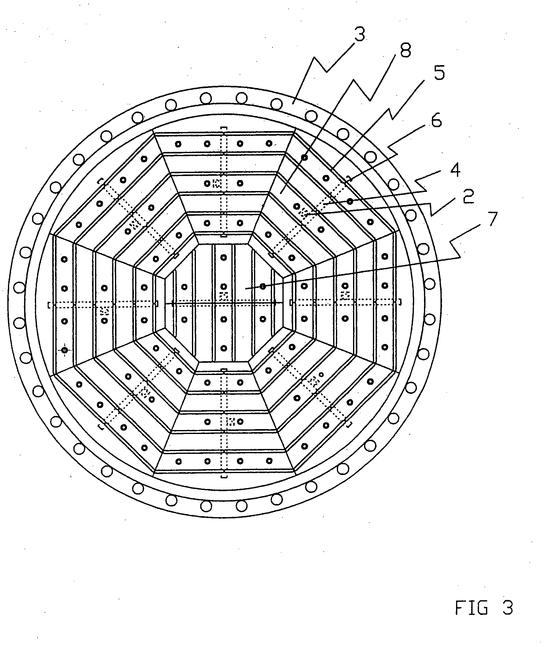
[0113] The test equipment included a column (such as for example in FIG. 7), a feed tank and an eluent tank, a feed solution pump and an eluent water pump and inlet valves for the both feed streams. The equipment included also a density meter (Micro Motion) to measure flow and density of the out coming flow and a flow control unit to control feed and eluent flows to the column. Pressure gauges were also placed in the column to measure liquid pressures at selected points: inlet liquid pressure (P1) and liquid pressure of resin bed after feed device (P2). Liquid pressure gauge P2 was isolated from the resin bed with a screen net.

[0114] The height of the column filling material bed was 1.0 m and diameter of the column filling material bed was 1.0 m. The column was packed with a strong acid gel type cation exchange resin (MitsubishiUBK 530) in Na+-form.

[0115] As a feed, 10 weight-% pure sucrose solution was used. The feed and the eluent water were used at a tempera...


PUM

PropertyMeasurementUnit
diameteraaaaaaaaaa
diameteraaaaaaaaaa
diameteraaaaaaaaaa

Abstract

The present invention relates to a fluid distributing device for distributing fluid into a column and to a fluid collecting device for collecting fluid from a column. The invention relates also to methods of using the devices of the present invention. The distributing device and / or the collecting device of the present invention can be used in fixed or fluidized bed reactors or columns, such as chromatographic separation columns, ion exchange columns, adsorption columns etc. A fluid distributing device comprises a) a first fluid conveying system; and b) a distributing plate, which comprises i) first means for fluid transfer for dividing the fluid flow coming from the delivering points into several partial fluid flows and for distributing the partial fluid flows into the column; and ii) first means for controlling of the partial fluid flows by differential pressure in the first means for fluid transfer.

Description

FIELD OF THE INVENTION [0001] The present invention relates to a fluid distributing device for distributing fluid into a column. The present invention relates also to a fluid collecting device for collecting fluid from a column. The invention relates also to methods of using the devices of the present invention. [0002] The distributing device and / or the collecting device of the present invention can be used in fixed or fluidized bed reactors or columns, such as chromatographic separation columns, ion exchange columns, adsorption columns etc. BACKGROUND OF THE INVENTION [0003] A common problem associated with the distributing devices is that the fluid to be distributed is introduced to a column through a pipe, which has a relatively small diameter compared to the diameter of the column. The fluid has to be distributed evenly over the entire cross-section area of the column and with minimum time delay and time delay distribution. Likewise a collecting device should collect fluid from ...

Claims


Application Information

Patent Timeline
Patent Type & Authority Applications(United States)
IPC IPC(8): B01D15/08B01D15/14G01N30/60
CPCB01D15/14G01N30/6017
Inventor PAANANEN, HANNUHEIKKILA, HEIKKILEWANDOWSKI, JARIVARTEVA, ESKO
Owner FINPHIDE
Why Eureka
Try Eureka