Reinforcement device for vehicle

a technology for enhancing devices and vehicles, which is applied in vehicular safety arrangments, roofs, transportation and packaging, etc., can solve the problems difficult to service the engine and other equipment positioned in the engine compartment without removing the reinforcing components, and reducing the available leg room for passengers. , the effect of reducing the available leg room for passengers

Active Publication Date: 2006-06-15
YAMAHA MOTOR CO LTD
View PDF21 Cites 15 Cited by
  • Summary
  • Abstract
  • Description
  • Claims
  • Application Information

AI Technical Summary

Benefits of technology

[0009] In some configurations, reinforcing members have been provided that extend side-to-side within the passenger compartment, or cabin, of the associated automobile. Such a configuration, however, is unsightly and reduces the available leg room for passengers.
[0010] Accordingly, one aspect of the present invention involves providing a reinforcement device for a vehicle, which device can easily improve the handling of the vehicle. The device preferably can be attached without a significant change in the body structure of the existing vehicle and without decreasing the serviceability of the engine or reducing the leg room of vehicle occupants.

Problems solved by technology

However, because the engine compartment has little available space for reinforcing components and because the hood height is limited, mounting the reinforcing components within the engine compartment can be problematic.
In addition, because the reinforcing components extend across the upper portion of the engine compartment, servicing the engine and other equipment positioned in the engine compartment can be difficult without removing the reinforcing components.
Such a configuration, however, is unsightly and reduces the available leg room for passengers.

Method used


Image

  • Reinforcement device for vehicle
  • Reinforcement device for vehicle
  • Reinforcement device for vehicle

Examples


Embodiment Construction

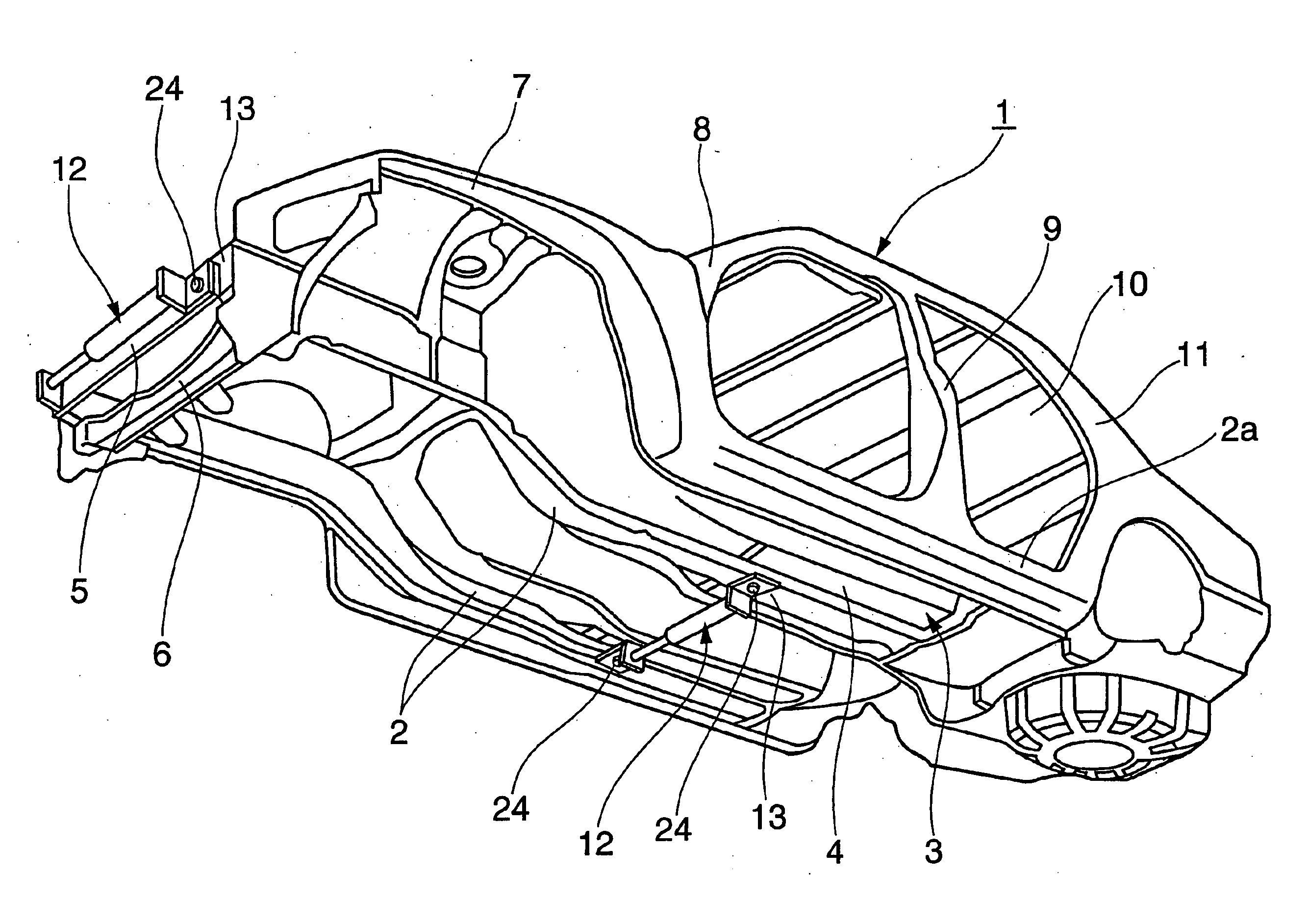
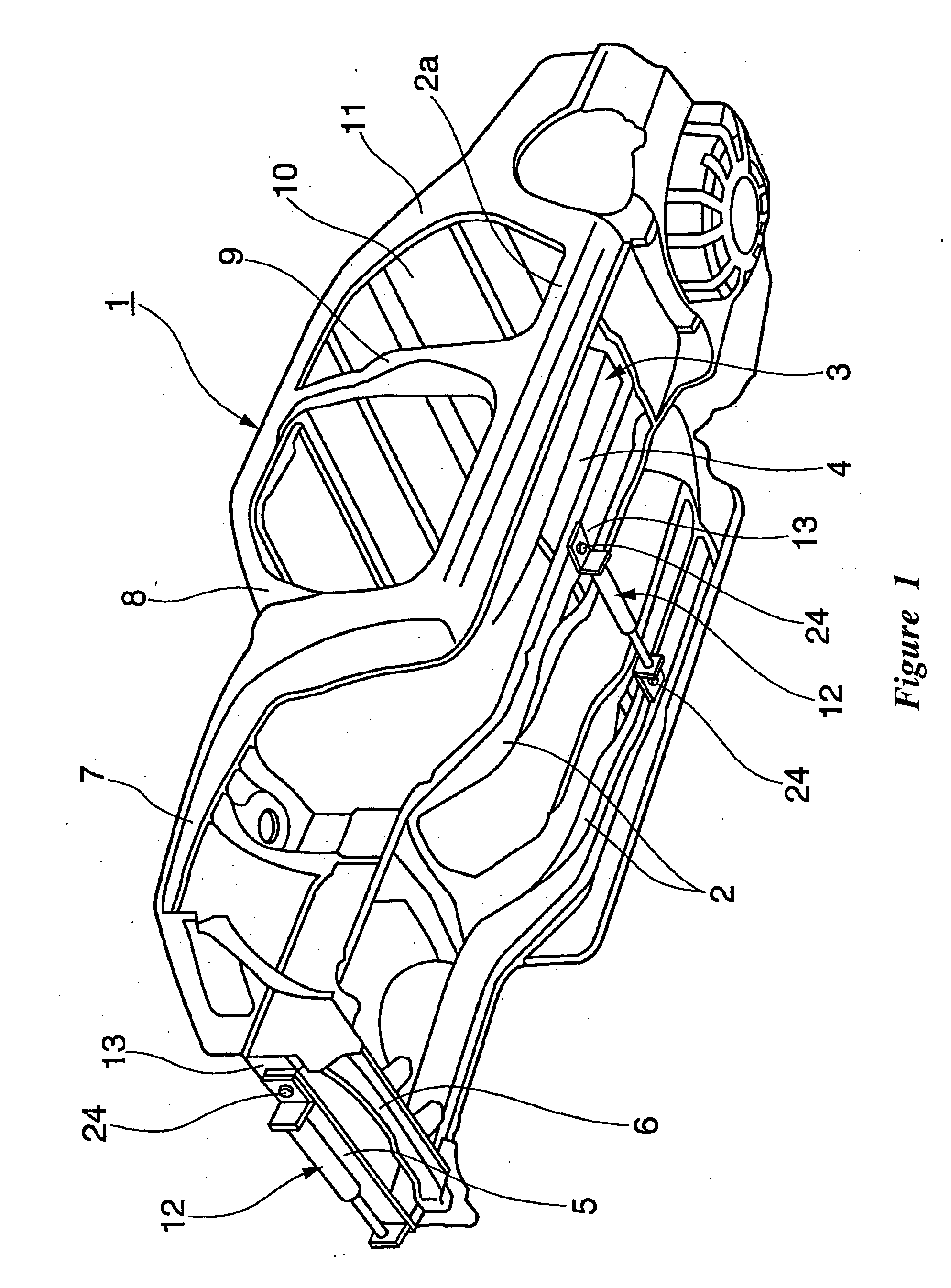
[0024] With reference now to FIG. 1, a body frame 1 is illustrated therein. The frame 1 preferably is formed as a monocoque body or a unibody construction. The monocoque body 1 typically is formed of a plurality of pressed plates or pipes that are assembled together and welded or bolted into position. In some applications, however, the frame 1 can be formed as a body-on-frame style or a partial monocoque body with a subframe. Other frame configurations also can be used.

[0025] The frame 1 preferably comprises two side frame rails 2. The illustrated side frame rails 2 extend in a longitudinal direction of the vehicle and are spaced in a transverse direction of the vehicle. More preferably, the side frame rails 2 extend along the two lateral sides of the vehicle. The illustrated frame 1 also comprises a floor panel 4 that, together with these side frame rails 2, defines an undercarriage or under body 3.

[0026] As illustrated, a bumper reinforcement 5 can be disposed toward an end of t...


PUM


Abstract

A reinforcement device for a vehicle is formed in a slender shape and comprises a medial region with a hydraulic damper. The damper generates a damping force against deformation in the longitudinal direction. The longitudinal direction is defined as a lateral direction of the associated vehicle body. The reinforcement device is removably mounted at both ends to a frame of the vehicle

Description

CROSS-REFERENCE TO RELATED APPLICATIONS [0001] The present application is based on and claims priority under 35 U.S.C. ∅ 119 Japenese Patent Application No. 2004-361120, filed on Dec. 14, 2004, the entire contents of which is expressly incorporated by reference herein.BACKGROUND OF THE INVENTION [0002] 1. Field of the Invention [0003] The present invention generally relates to a vibration-damping reinforcement device for a vehicle. More particularly, the present invention relates to such a reinforcement device that comprises a damping cylinder assembly. [0004] 2. Description of the Related Art [0005] An aftermarket reinforcement member such as that disclosed in U.S. Pat. No. 5,411,311 is used to stiffen vehicle frames. These components commonly are called strut tower bars. The strut tower bar is designed to be mounted between upper portions of a body frame of the vehicle. In particular, the strut tower bar extends between the strut towers, which are positioned in the engine compartm...

Claims


Application Information

Patent Timeline
Patent Type & Authority Applications(United States)
IPC IPC(8): B62D21/00B60J7/00
CPCB60G2206/014B60G2206/605B60R19/00B62D21/15B62D21/157B62D25/2009B62D25/2036
Inventor KONDOU, KATSUHIROSATOU, MASAHIRO
Owner YAMAHA MOTOR CO LTD
Why Eureka
Try Eureka