Method and apparatus for estimating rotor position and for sensorless control of a switched reluctance motor
a technology of closed loop control and rotor position, which is applied in the direction of motor/generator/converter stopper, dynamo-electric converter control, machine/engine, etc., can solve the problem of high cost of shaft position sensors
- Summary
- Abstract
- Description
- Claims
- Application Information
AI Technical Summary
Benefits of technology
Problems solved by technology
Method used
Image
Examples
first exemplary embodiment
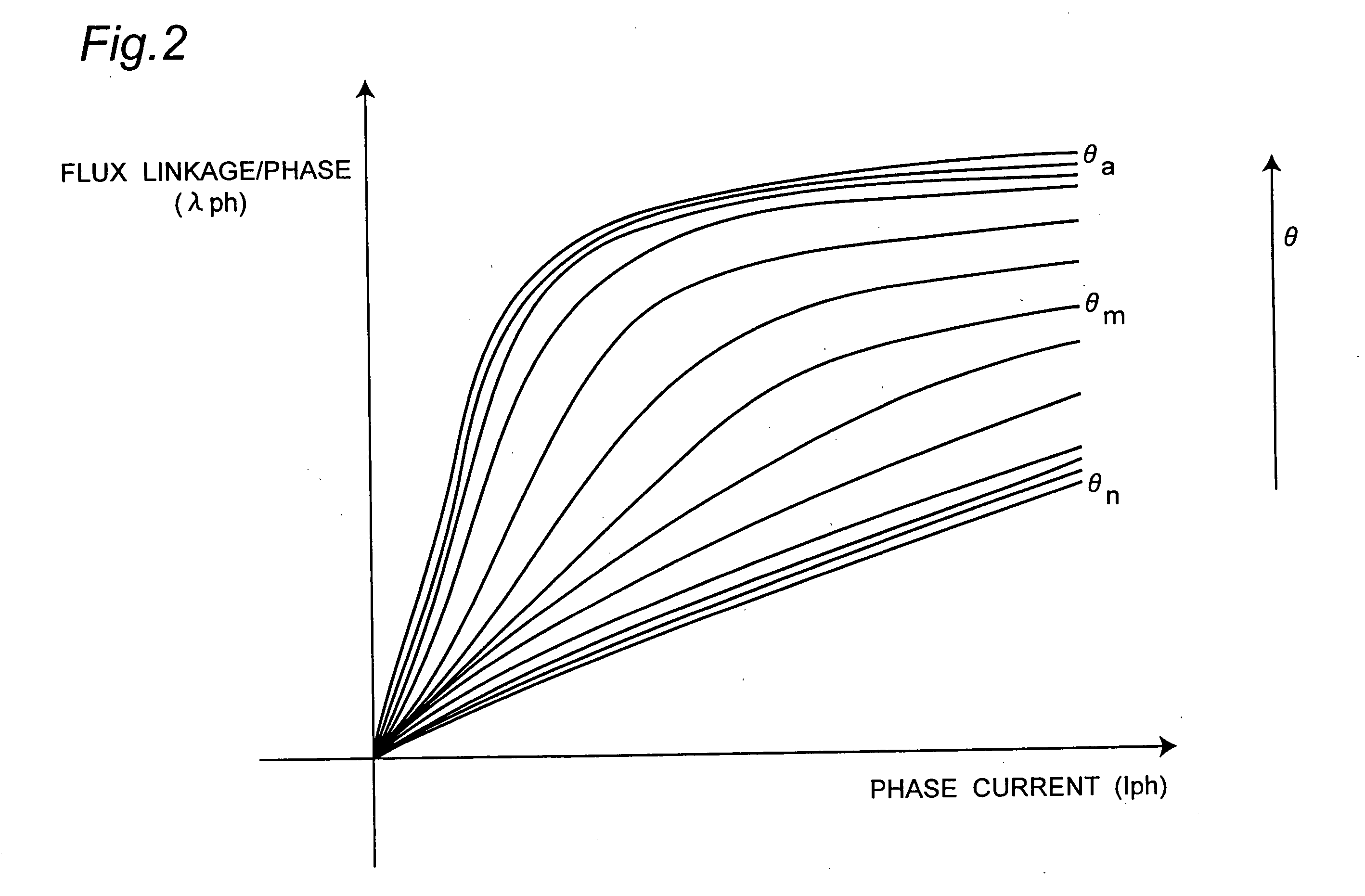
[0046] In the discrete rotor position estimation technique I, the per phase flux-linkage λph is calculated on-line in every PWM interrupt or every PWM half-cycle interrupt by sensing the d.c.-link voltage Vdc and the phase current Iph and is defined by the equation (7) above. The incremental change of per phase flux-linkage λph at the valley of every PWM interrupt of the processor is shown in FIG. 8 where dt is the time interval between two PWM interrupts and θon is the turn-on angle and θoff is the turn-off angle. Any digital technique cannot exactly define the instant when the per phase flux-linkage λph is equal to the reference flux-linkage λr. In this embodiment, the processor within a PWM interrupt identifies an instant when the per phase flux-linkage λph is greater than λr as shown in FIG. 8. Therefore, for more accurate rotor position estimation, θabs of equation (8) in the discrete rotor position technique I has to be modified. In the simplest technique, the modification of ...
second exemplary embodiment
[0057]FIG. 11 shows an entire block diagram of a driving apparatus of SRM for achieving the closed loop control with a control strategy II according to the invention.
[0058] In the control strategy II involving the discrete rotor position estimation technique I, instead of calculating θest continuously to control the turn-on and turn-off angle the incremental rotor displacement Δθ in every PWM interrupt can be calculated in an alternative way which can generate appropriate delays to turn-off the active phase and turn-on the next phase. The speed (ω) of the motor is also calculated from the incremental rotor angle Δθ (by block 16), and the closed loop control can be executed in the similar manner described in the first exemplary embodiment. In the control strategy II, Δθ can be calculated by counting the number of PWM interrupts between two consecutive instants when the per phase flux-linkage λph is greater than the reference flux-linkage λr (by blocks 13a and 15a), that is, between ...
third exemplary embodiment
[0062] The discrete rotor position estimation technique I described in the first and the second exemplary embodiment includes comparing the per phase flux-linkage λph with only one reference flux-linkage λr defined for a rotor position θr. Hence, in both cases, exact rotor position θcal and incremental rotor angle Δθ are calculated only once at the instant when the per phase flux-linkage λph is greater than the reference flux-linkage λr during the conduction of each active phase. The discrete rotor position estimation technique I can be extended by defining two reference flux-linkages λr1 and λr2 at rotor positions θr1 and θr2 respectively as shown in FIG. 12A or three reference flux-linkages λr1, λr2 and λr3 at rotor positions θr1, θr2 and θr3 respectively as shown in FIG. 12B by polynomial expression in phase current Iph. All these rotor positions lie near the mid-position θm with a deviation angle αmax of 30°. Hence, the on-line estimated per phase flux-linkage λph is compared wi...
PUM
 Abstract
Description
Claims
Application Information
 - R&D
- Intellectual Property
- Life Sciences
- Materials
- Tech Scout
- Unparalleled Data Quality
- Higher Quality Content
- 60% Fewer Hallucinations
Browse by: Latest US Patents, China's latest patents, Technical Efficacy Thesaurus, Application Domain, Technology Topic, Popular Technical Reports.
© 2025 PatSnap. All rights reserved.Legal|Privacy policy|Modern Slavery Act Transparency Statement|Sitemap|About US| Contact US: help@patsnap.com


