

Lift detection mechanism for optical mouse sensor
- Summary
- Abstract
- Description
- Claims
- Application Information
AI Technical Summary
Benefits of technology
Problems solved by technology
Method used
Image

Examples
first embodiment
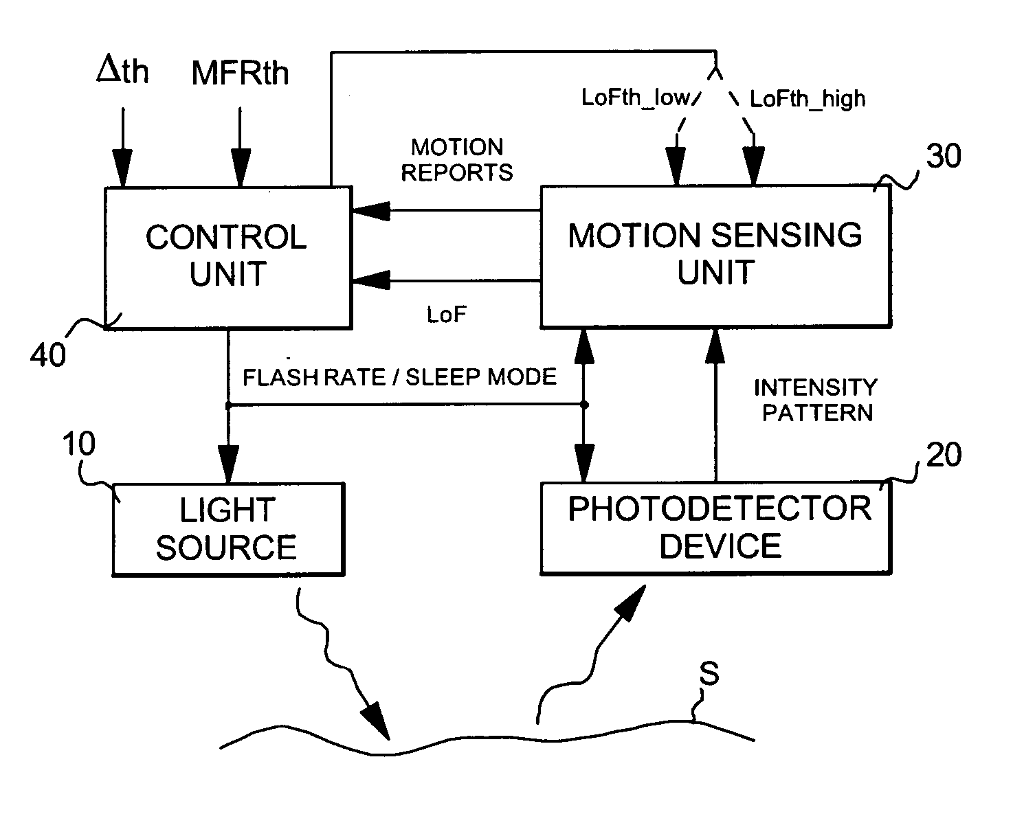
[0022]FIG. 1 illustrates schematically an optical motion sensing device according to the present invention. It basically consists in an optical sensing system comprising a light source 10 for illuminating a portion of a surface S with radiation, a photodetector device 20, which may be a photodetector array including a plurality of pixels aligned along two axes, responsive to radiation reflected from the illuminated surface portion S, and a motion sensing unit 30, coupled to the output of photodetector device 20, for detecting and measuring relative motion of the optical motion sensing device with respect to the illuminated surface portion S.
[0023] During each period of activation, or flash, light source 10 is activated to illuminate the surface portion S, photodetector device 20 is activated to capture an image or intensity pattern of the illuminated surface portion S and motion sensing unit 30 is activated to detect and measure relative motion with respect to the illuminated surfac...
second embodiment
[0049]FIG. 3 is a schematic illustration of an optical motion sensing device according to the present invention. Like in FIG. 1, it shows light source 10 for illuminating portion surface S with radiation, photodetector device 20 responsive to radiation reflected from the illuminated surface portion, motion sensing unit 30 coupled to photodetector device 20 for detecting and measuring a relative motion with respect to the illuminated surface portion.
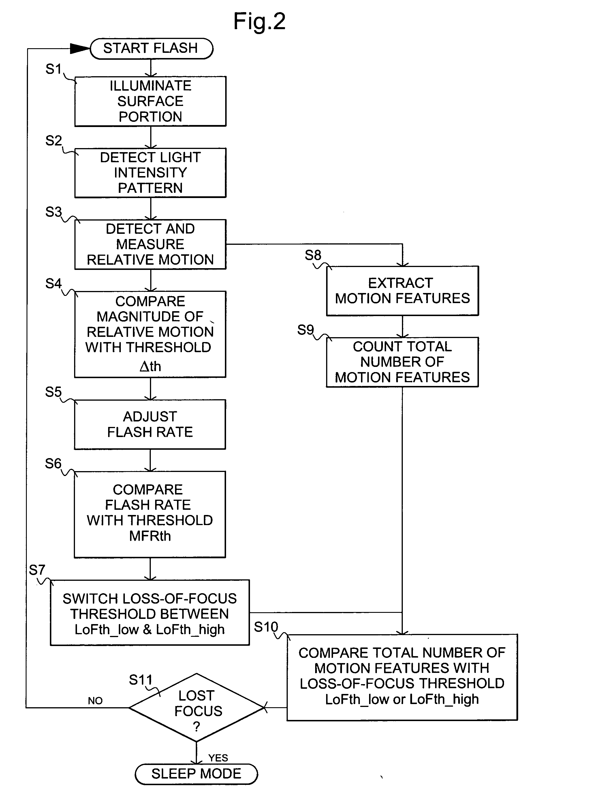
[0050] Motion sensing unit 30 is further adapted to extract motion features from the detected relative motion and count a total number of the extracted motion features. The total number of motion features is sent to control unit 40 for each flash period. Control unit 40 computes an average value (A) with at least some of the previous total number of motion features received over a sliding predetermined period of time. For example, the computing function can be an average value of the last N total numbers of motion features received. Accor...
PUM
 Abstract
Description
Claims
Application Information