
Color micro-mirror projectors

Inactive Publication Date: 2006-06-15
HON HAI PRECISION IND CO LTD
View PDF4 Cites 3 Cited by
  • Summary
  • Abstract
  • Description
  • Claims
  • Application Information

AI Technical Summary

Benefits of technology

[0008] In one embodiment, a micro-mirror projector includes a light source, a converging member, a color wheel, a shaping member, a micro-mirror chip, a diffraction member and a projection member. The color wheel has at least red, green and blue segments. The micro-mirror chip has a plurality of digital micro-mirror members and a processor formed thereon. Each micro-mirror member has a plurality of micro-mirrors formed thereon. The light source is used to emit a light beam. The converging member is used to converge the light beam to the color wheel. The color wheel rapidly rotates across the converged light beam to generate red, green and blue lights. The shaping member is used to shape the red, green and blue lights as parallel lights and transmit the parallel lights to a corresponding micro-mirror member of the micro-mirror chip. The micro-mirror member receives a controlling signal from the processor. Upon being signaled to do so, the micro-mirrors thereon rapidly rotate and respectively transmit the corresponding parallel lights to the diffraction member at a given / selected time. The diffraction member is used to diffract the received lights to the projection member. The projection member is used to transmit the diffracted lights onto a projection screen. The diffracted lights are relatively fine, thereby generating a better display on the projection screen.
[0009] Compared with a conventional micro-mirror projector, the light transmitted to the projection member of the present micro-mirror projector is relatively fine (i.e., highly resolved) due to the diffracting effect of the diffraction member. That is to say, energy loss of the light is relatively little. Therefore, divisions between adjacent pixels are relatively dim (i.e., not highly pronounced; essentially indistinct). Thus, images displayed on the projection screen are better (i.e., with respect to the brightness, chroma / vividness, and / or uniformity thereof).

Problems solved by technology

This results in the image being unsatisfactory.

Method used


Image

  • Color micro-mirror projectors
  • Color micro-mirror projectors
  • Color micro-mirror projectors

Examples


Embodiment Construction

[0016] Reference will now be made to the drawings to describe embodiments of the present micro-mirror projector in detail.

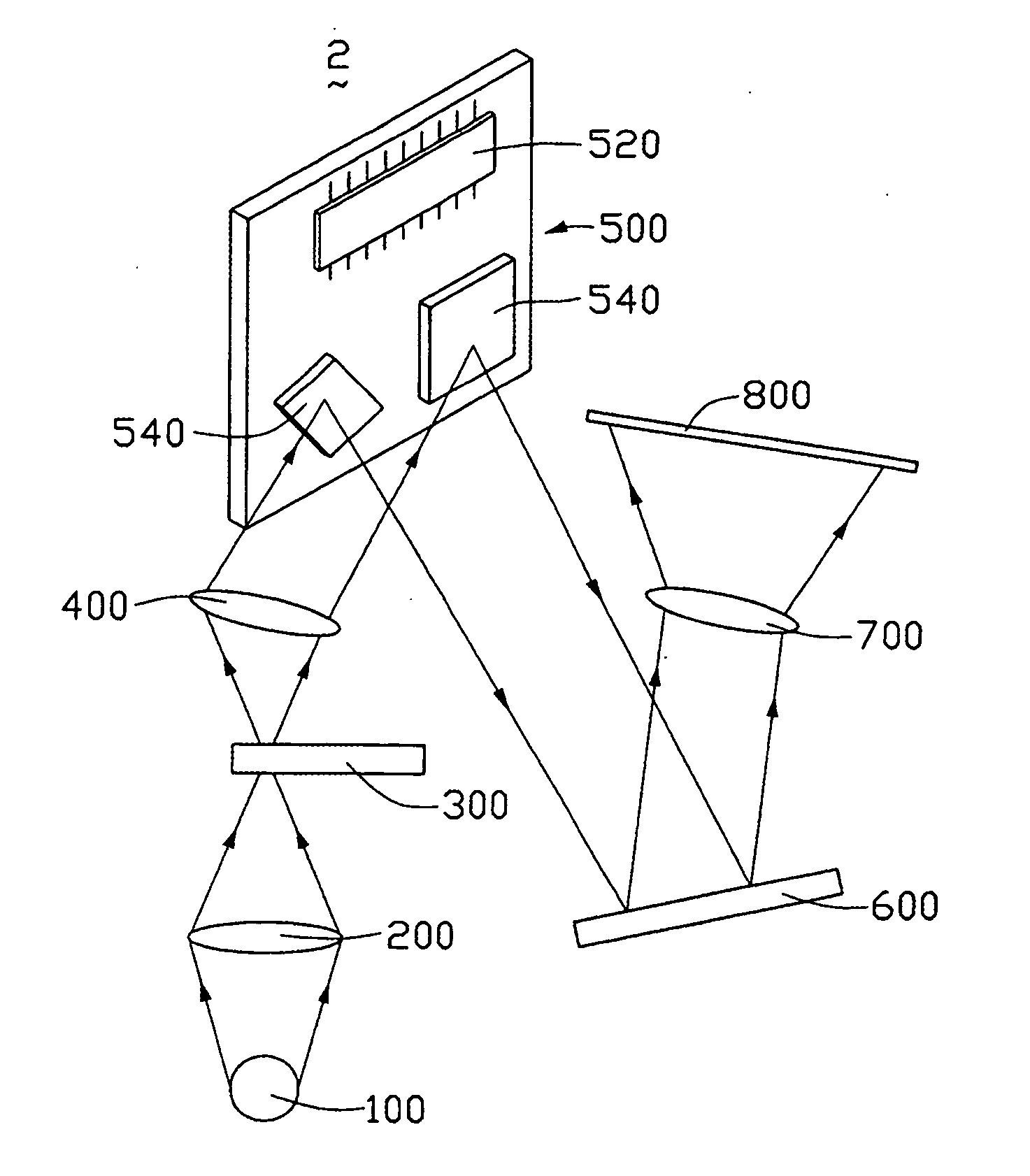
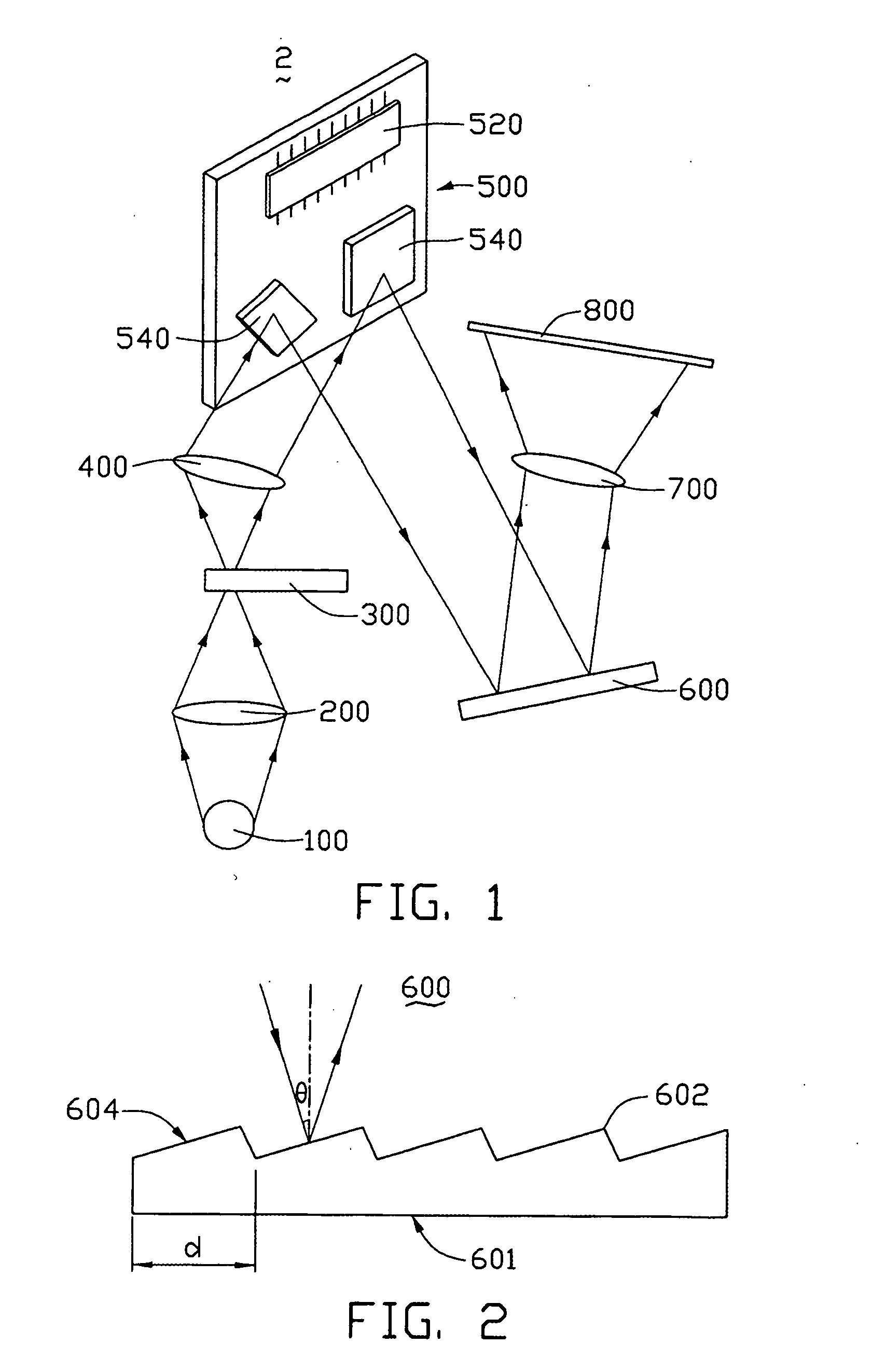
[0017] Referring to FIG. 1, a micro-mirror projector 2, in accordance with a preferred embodiment of the present device, includes a light source 100, a converging member 200, a color wheel 300, a shaping member 400, a micro-mirror chip 500, a diffraction member 600 and a projection member 700. The color wheel 300 includes at least three color segments. In the preferred embodiment, the color wheel 300 includes red, green and blue segments. The micro-mirror chip 500 has a plurality of micro-mirror members 540 and a processor 520 formed thereon. Each micro-mirror member 540 has a plurality of micro-mirrors (not shown) formed thereon. The processor 520 is used to control the rotation of the micro-mirrors. In the preferred embodiment, the converging member 200 is a converging lens, the shaping member 400 is a shaping lens, and the diffraction member 600 is a diffract...


PUM


Abstract

A micro-mirror projector (2) includes a light source (100), a converging member (200), a color wheel (300) having red, green and blue segments, a shaping member (400), a micro-mirror chip (500) having a plurality of micro-mirror members (540) formed thereon, a diffraction member (600), and a projection member (700). The converging member converges a light beam emitted from the light source to the color wheel. The color wheel rotates across the converged light beam to generate red, green and blue lights. The shaping member shapes the red, green and blue lights as parallel lights and transmits the parallel light to a corresponding micro-mirror member. The micro-mirror member transmits the parallel lights to the diffraction member. The diffraction member diffracts the received lights to the projection member. The diffracted light is relatively fine / highly resolved, thereby resulting in a better display on a projection screen (800) via the projection member.

Description

BACKGROUND [0001] 1. Field of the Invention [0002] The present invention relates generally to color display devices and, more particularly, to a color micro-mirror projector. [0003] 2. Discussion of Related Art [0004] Micro-mirror projectors are also called digital light processing (DLP) projection devices. Micro-mirror projectors have been developed by Texas Instruments, and a typical micro-mirror projector adopts digital micro-mirror devices (DMDs) to control light beams to enter the display light path. A typical DMD includes a plurality of supporting posts, a plurality of torsion hinges, and a plurality of micro-mirrors formed on a semiconductor substrate thereof. The semiconductor substrate can be, e.g., a silicon substrate. Each torsion hinge is positioned between two adjacent supporting posts, and each micro-mirror is installed on a given torsion hinge. When controlling signals are input to the DMD, the micro-mirrors would rotate around the corresponding torsion hinges. [0005]...

Claims


Application Information

Patent Timeline
IPC IPC(8): G03B21/00
CPCG03B21/14G03B21/28H04N9/3114G03B21/008G03B21/208G03B33/08
Inventor CHEN, GA-LANE
Owner HON HAI PRECISION IND CO LTD
Features
  • Generate Ideas
  • Intellectual Property
  • Life Sciences
  • Materials
  • Tech Scout
  • Unparalleled Data Quality
  • Higher Quality Content
  • 60% Fewer Hallucinations
Learn More