
Electronic equipment

a technology of electronic equipment and casings, applied in the direction of electrical apparatus casings/cabinets/drawers, coupling device connections, instruments, etc., can solve the problem of insufficient casings, and achieve the effect of reducing the steps of designing casings and production costs

Inactive Publication Date: 2006-06-15
PANASONIC CORP
View PDF6 Cites 41 Cited by
  • Summary
  • Abstract
  • Description
  • Claims
  • Application Information

AI Technical Summary

Benefits of technology

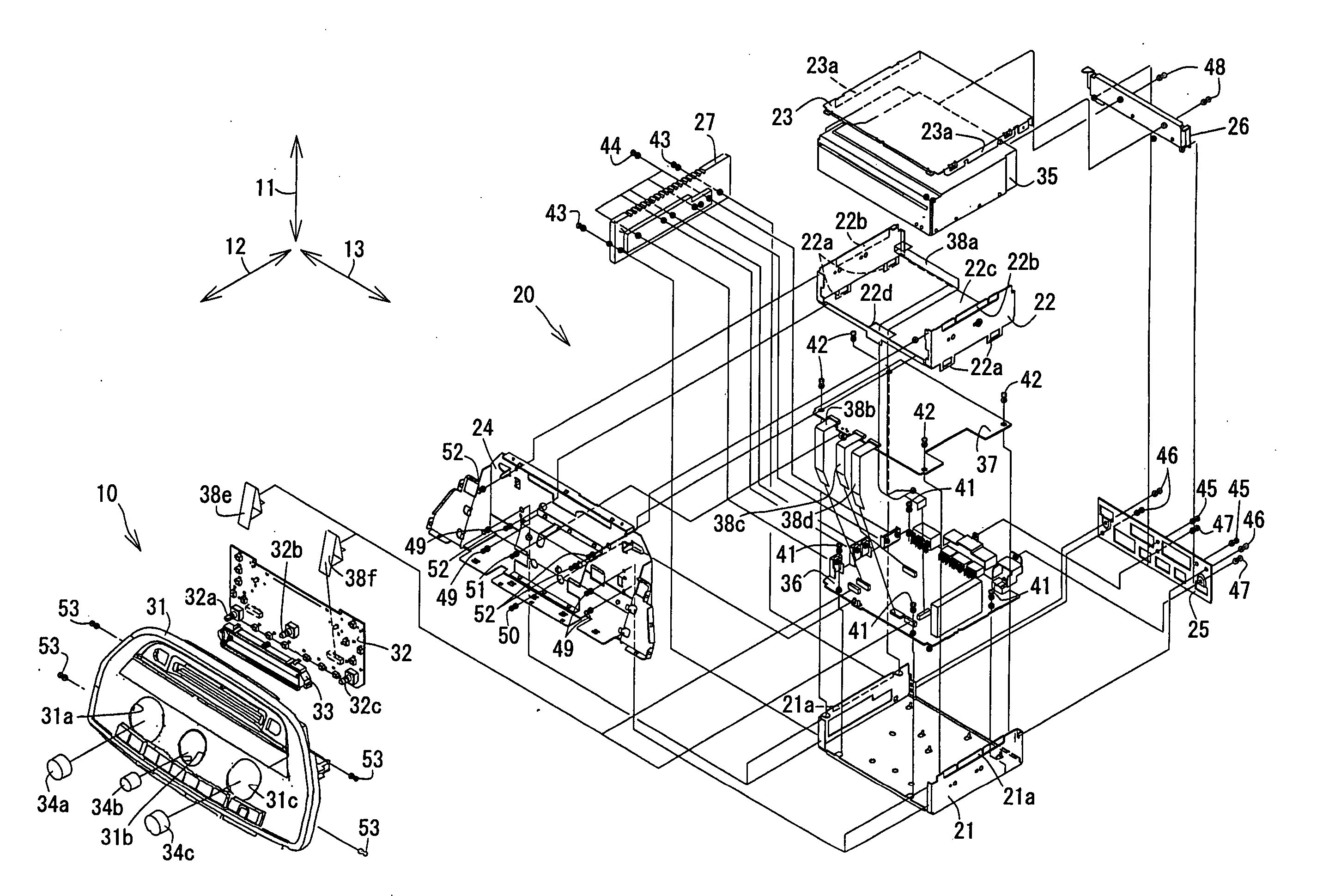
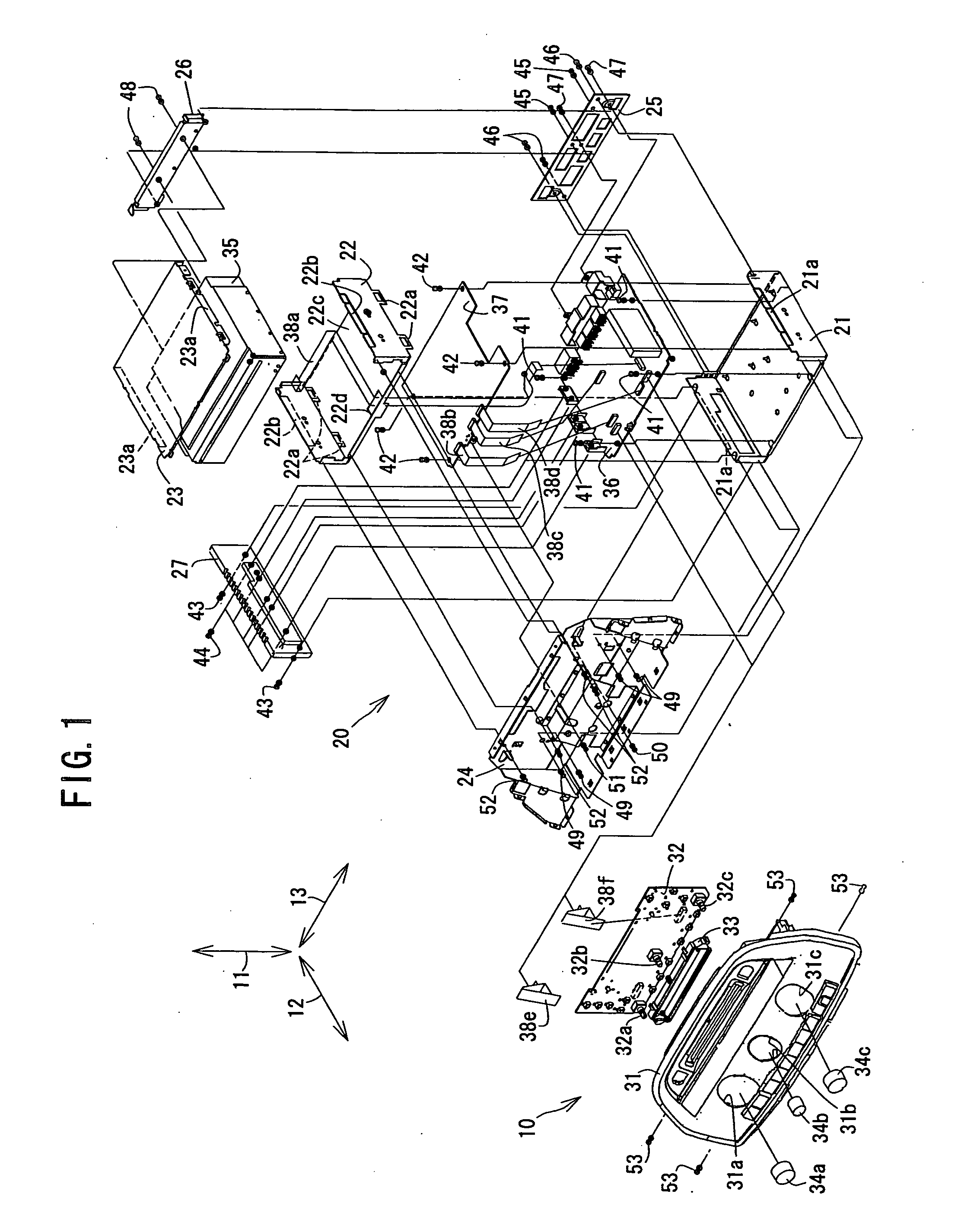
[0006] The common case member is available for not only a part of the double length case but also a part of the standard length case different in size from said double length case. It is therefore possible to reduce steps of designing cases and the production cost of parts of the cases and their dies in comparison with the conventional common case unavailable for a case different in size from the double length case.
[0008] The common case member and the additional case member are prevented from separating from each other by means of the common side engaging portion and the additional side engaging portion held in press-fit contact with each other in a direction different from the predetermined direction. This fitting engagement including press-fit contact makes it possible to reduce the number of tightening members such as screws and the steps of fixedly connecting the common case member with the additional case member by the tightening members, as compared with another engagement by which the common case member and the additional case member are not prevented from separating from each other.
[0010] The connecting member disposed on one or the other side in a direction in which the common case member and the front panel are arranged makes it possible to increase the size of the double length case in a direction perpendicular to the direction in which the common case member and the front panel are arranged, in comparison with any one of other connecting members disposed on one or the other side in any one of directions perpendicular to the direction in which the common case member and the front panel are arranged, even in spite of the fact that there is a limit to the overall length of the double length case in the perpendicular directions.
[0014] The common side electronic part and the additional side electronic part are connected by the harness cable passing through the passage hole of the additional case member. The length of the harness cable between the common side electronic part and the additional side electronic part is reduced and shortened as compared with that of a harness cable for connecting the common side electronic part and the additional side electronic part without passing through the passage hole of the additional case member.
[0016] In this electronic equipment, the common side electronic part is shielded from an electromagnetic wave radiated from the additional side electronic part, or / and, the additional side electronic part is shielded from an electromagnetic wave radiated from the common side electronic part. This enables to prevent each of the common side electronic part and the additional side electronic part from being adversely affected by the electromagnetic wave and falling into a malfunction.
[0018] The cover member engageable with the common side engaging portion of the common case member is disposed on the opposite side of the additional case member as against the common case member to have the cover side engaging portion held in fitting engagement with the cover engaging portion of the additional case member. The cover member is available for the standard length case as well as the double length case. It is therefore possible for the cover member to reduce the steps of designing cases and the production cost of case parts and their dies in comparison with that of the conventional case unavailable for another cover different in case size from the double length case.

Problems solved by technology

The above-mentioned audio equipment, however, encounters such a problem that the common case is not available for an electronic equipment having a case different in size from the common case.

Method used


Image

  • Electronic equipment
  • Electronic equipment
  • Electronic equipment

Examples


Embodiment Construction

[0026] The electronic equipment according to the present invention will now be described in detail in accordance with a preferred embodiment shown in the accompanying drawings.

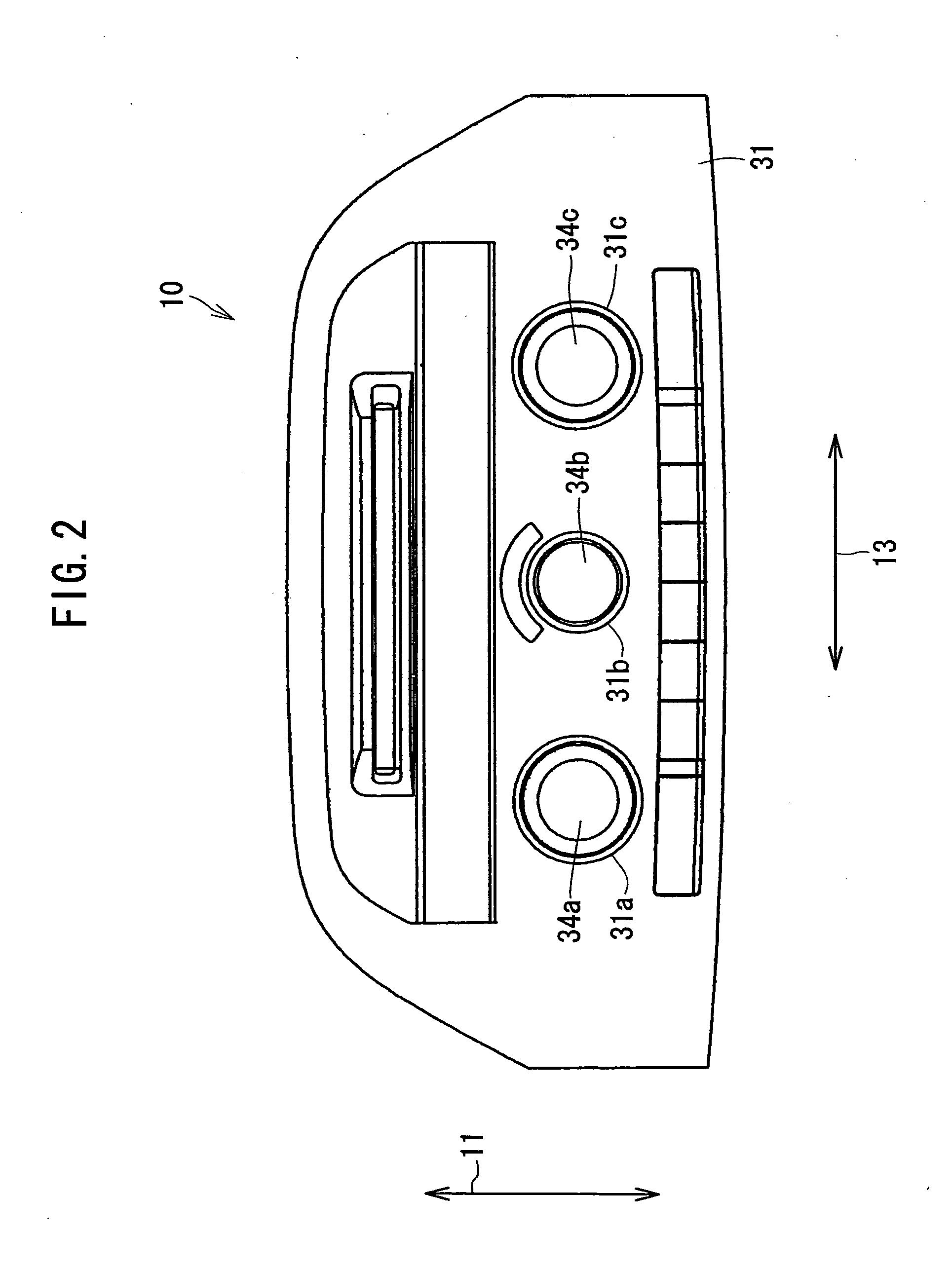
[0027] As shown in FIGS. 1 to 3, the present invention is exemplified in a preferred vehicle mountable electronic equipment 10, as comprising a double length case 20 having an overall length set at for example 2 DIN (Deutsche Institute Norm) size substantially twice as long as a predetermined standard length 10a (e.g., 1 DIN) in a predetermined direction shown by an arrow 11, a front panel 31 formed with a set of holes 31a, 31b and 31c and disposed on the front side of the double length case 20, a display circuit board 32 including a set of variable resistors 32a, 32b and 32c and disposed between the double length case 20 and the front panel 31, an LCD (Liquid Crystal Display) block 33 mounted on the display circuit board 32 and positioned between the front panel 31 and the display circuit board 32, a knob 34...


PUM


Abstract

Electronic equipment according to the present invention comprises a case having an overall length substantially twice as long as a predetermined standard length in a predetermined direction shown by an arrow. The case includes a bottom cover case shorter in overall length in the predetermined direction than the standard length and available for a part of a standard length case having in the predetermined direction an overall length identical to the standard length, and an intermediate cover case longer in overall length in the predetermined direction than the standard length case and disposed on a predetermined side of the bottom cover case. The bottom cover case has an engaging portion held in engagement with the intermediate cover case, and the intermediate cover case has an engaging portion held in engagement with the engaging portion of the bottom cover case.

Description

TECHNICAL FIELD [0001] The present invention relates to an electronic equipment comprising a common case available for a different type of electronic equipment. BACKGROUND ART [0002] Conventionally, there has been known an audio equipment comprising a common case available for that of another type of audio equipment (JPN unexamined patent publication No. 10-222971 (pages 2-3, FIGS. 1-2)), which further comprises a replaceable bezel plate designed to distinguish one type of audio equipment from others. [0003] The above-mentioned audio equipment, however, encounters such a problem that the common case is not available for an electronic equipment having a case different in size from the common case. [0004] It is therefore an object of the present invention to provide an electronic equipment comprising a common case member available for that of a different type of electronic equipment in the case that the electronic equipment and the different type of electronic equipment are different ...

Claims


Application Information

Patent Timeline
Patent Type & Authority Applications(United States)
IPC IPC(8): H02B1/00H05K7/00H04B1/08H05K5/02H05K9/00
CPCB60R11/02B60R13/0256B60R13/0275H04B1/082
Inventor IWANO, KENJIKUSUMOTO, KOJI
Owner PANASONIC CORP
Learn More