Matching receive signal strenth data associated with radio emission sources for positioning applications

a technology of receiving signal and positioning application, which is applied in the direction of transmission monitoring, instruments, measurement devices, etc., can solve the problems of wlans that can complicate existing network management schemes, provide little or no capability to manage frequency bands, and collapse the overall wireless utility (and user satisfaction)

Inactive Publication Date: 2006-06-15
CISCO TECH INC
View PDF18 Cites 142 Cited by
  • Summary
  • Abstract
  • Description
  • Claims
  • Application Information

AI Technical Summary

Benefits of technology

[0009] Briefly, a system, method and software are provided for determining a position of a source of a radio emission. Receive signal strength data associated with reception of radio emissions is generated at each of a plurality of radio sensor devices that are at corresponding known positions in an area where the radio emissions are occurring. Using characteristics associated with reception of the radio emissions at each of the sensor devices, the receive signal strength data generated by each of the sensors is matched as corresponding to a radio emission from the same source. The characteristics used to match receive signal strength data may include spectrum analysis data and / or timing analysis data. Once the receive signal strength data is matched, position computations may be performed on the appropriate set of receive signal strength data to compute the position of the source of the radio emission.

Problems solved by technology

It is well recognized that as unlicensed band devices become more popular and their density in a given area increases, a “tragedy of the commons” effect will often become apparent and overall wireless utility (and user satisfaction) will collapse.
WLANs can complicate existing network management schemes because they introduce the additional requirement of efficiently managing radio spectrum.
Current WLAN systems and management technology are focused on managing activity at the network level of the WLAN, but provide little or no capability to manage the frequency band where signals of multiple types (e.g., communication protocol / network types, device types, etc.) are present.
The types of signaling protocols used by devices in the unlicensed bands are not designed to cooperate with signals of other types also operating in the bands.
For example, a frequency hopping signal (e.g., a signal emitted from a device that uses the Bluetooth™ communication protocol or a signal emitted from certain cordless phones) may hop into the frequency channel of an IEEE 802.11 wireless local area network (WLAN), causing interference with operation of the WLAN.

Method used


Image

  • Matching receive signal strenth data associated with radio emission sources for positioning applications
  • Matching receive signal strenth data associated with radio emission sources for positioning applications
  • Matching receive signal strenth data associated with radio emission sources for positioning applications

Examples


Embodiment Construction

[0023] The system, methods, software and other technologies described herein are designed to cooperatively manage use of a shared frequency band where signals of multiple types occur (often simultaneously), such as an unlicensed band, and interference among the users of the band may occur. Many of the concepts described herein may apply to frequency bands that are not necessarily “unlicensed,” such as when a licensed frequency band is used for secondary licensed or unlicensed purposes.

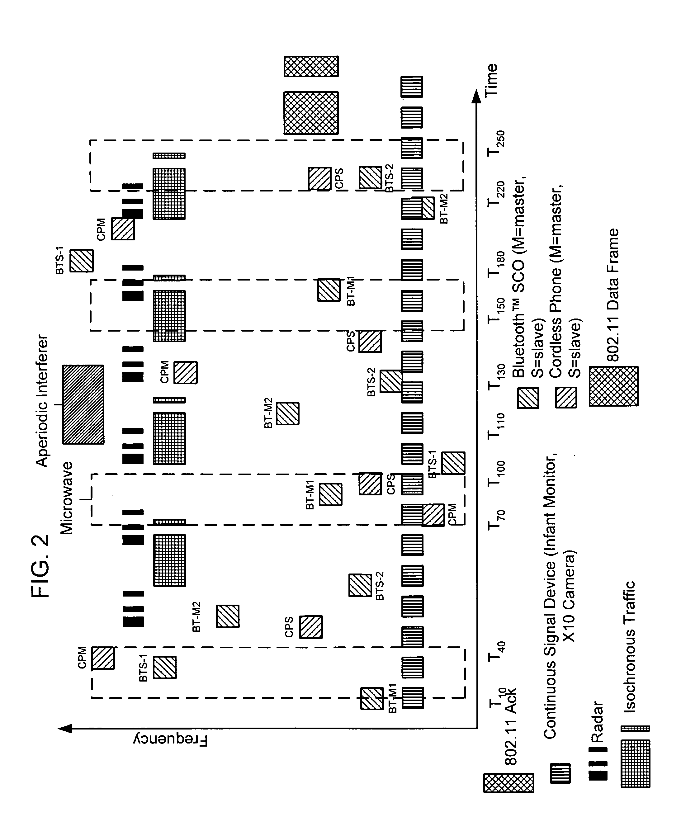
[0024] The term “network” is used hereinafter in many ways. There may be one or more wireless networks each comprising multiple devices or nodes that operate in the shared frequency band. One example of such a network is a WLAN. There are also networks, called piconets, which are formed with Bluetooth™ (master and slave) devices. Many of the examples described herein are made with respect to an IEEE 802.11 (also known as WiFi™) WLAN, mostly due in part to the expansive use that the WLAN has seen, and ...


PUM


Abstract

A system, method and software for determining a position of a source of a radio emission. Receive signal strength data associated with reception of radio emissions is generated at each of a plurality of radio sensor devices that are at corresponding known positions in an area where the radio emissions are occurring. Using characteristics associated with reception of the radio emissions at each of the sensor devices, the receive signal strength data generated by each of the sensors is matched as corresponding to a radio emission from the same source. The characteristics used to match receive signal strength data may include spectrum analysis data and/or timing analysis data. Once the receive signal strength data is matched, position computations may be performed on the appropriate set of receive signal strength data to compute the position of the source of the radio emission.

Description

RELATED APPLICATIONS [0001] This application is related to the following commonly assigned and co-pending applications: [0002] U.S. application Ser. No. 10 / 717,852, filed Nov. 19, 2003, entitled “Server and Multiple Sensor System for Monitoring Activity in a Shared Radio Frequency Band”. [0003] U.S. application Ser. No. 10 / 909,455, filed Aug. 2, 2004, entitled “Automated Real-Time Site Survey in a Shared Frequency Band Environment”.BACKGROUND OF THE INVENTION [0004] The explosive growth in wireless applications and devices over the past few years has produced tremendous public interest benefits. Wireless networks and devices have been deployed in millions of offices, homes, and more recently, in increasing numbers of public areas. These wireless deployments are forecast to continue at an exciting pace and offer the promise of increased convenience and productivity. [0005] This growth, which is taking place mostly in the unlicensed bands, is not without its downsides. In the United S...

Claims


Application Information

Patent Timeline
Patent Type & Authority Applications(United States)
IPC IPC(8): H04B17/00
CPCG01S5/0252
Inventor TESFAI, YOHANNES
Owner CISCO TECH INC
Why Eureka
Try Eureka