Variable view arthroscope with charge coupled device

a charge-coupled device and variable view technology, applied in the field of variable view arthroscopes, can solve the problems of limited field of view afforded by even the best commercially available instruments, the use of minimally invasive techniques, and the limitations of the principal optical instruments employed, so as to reduce the cost and complexity of a variable view arthroscop

Inactive Publication Date: 2006-06-15
DURELL & GITELIS INC
View PDF32 Cites 17 Cited by
  • Summary
  • Abstract
  • Description
  • Claims
  • Application Information

AI Technical Summary

Benefits of technology

[0008] The present invention is directed to a variable view arthroscope with a plurality of viewing positions in a viewing range between a first end viewing position and a second end viewing position. In certain embodiments, a variable view arthroscope includes a tubular housing having a longitudinal axis and an input end, an input lens and a mirror in the housing for obtaining an image object, and a prism, a focusing lens, and a CCD in the housing for capturing and relaying the image object. The input lens and mirror are movable around an axis for varying the view of the arthroscope.
[0009] In some embodiments, a variable view arthroscope includes a tubular housing having a longitudinal axis and an input end, an input lens and a CCD in the housing for capturing and relaying the image object. In certain embodiments, the tubular housing has a longitudinal axis and an input end and the input lens and CCD are mounted in an input lens holder in the input end of the housing. The input lens and the CCD are movable for varying the view of the arthroscope.
[0010] The CCD converts the object image into a digital image that can be viewed, for example, on a TV or CRT screen. The CCD can be used to replace a field and relay system, or additional focusing lenses and mirrors, thereby decreasing the cost and complexity of a variable view arthroscope. Various mechanisms can be provided for moving the optical elements, including the CCD in some embodiments, to vary the view of the arthroscope.

Problems solved by technology

One drawback of these minimally invasive techniques derives from the technical limitations of the arthroscopes, endoscopes and other principal optical instruments employed.
In particular, one significant limitation is the limited field of view afforded by even the best commercially available instruments; in some respects these instruments and techniques have not changed significantly since the 1980s.
Generally, such proposals have entailed the packing of a plurality of movable lenses or prisms into the input end of the instrument, posing numerous design challenges and often resulting in various problems, such as precision of construction, precision of relative movements, space requirements, optical distortions, and elimination of undesired “ambient” light.

Method used


Image

  • Variable view arthroscope with charge coupled device
  • Variable view arthroscope with charge coupled device
  • Variable view arthroscope with charge coupled device

Examples


Embodiment Construction

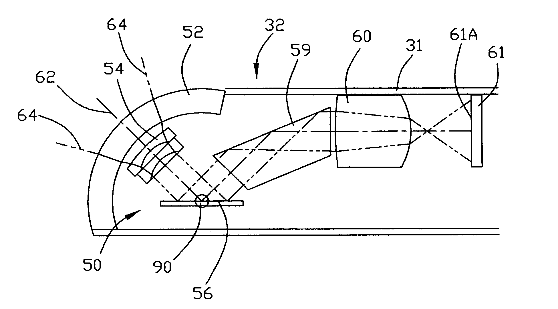
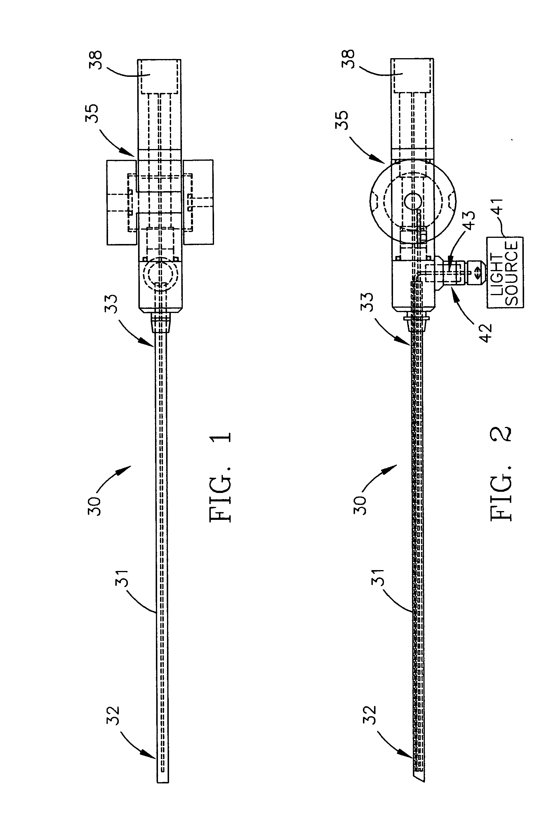
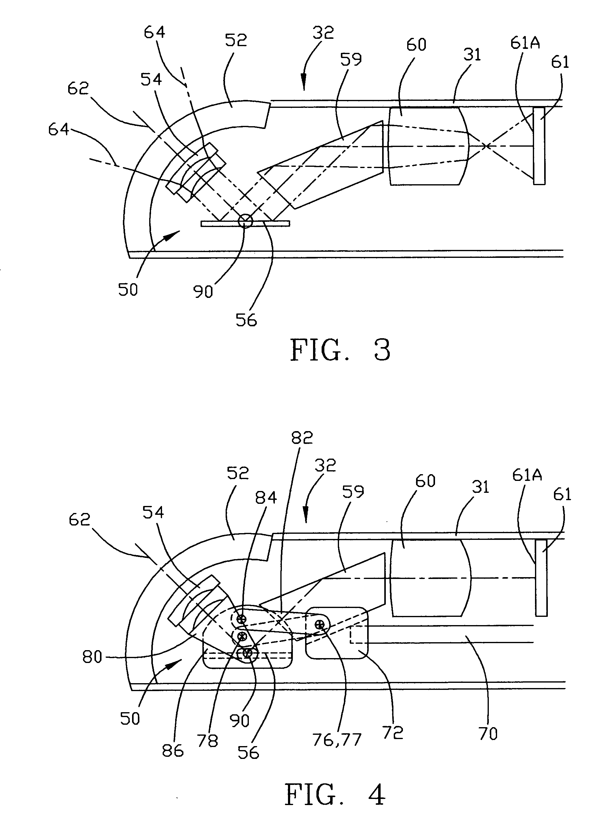
[0018] A variable view arthroscope in which various embodiments of the present invention can be incorporated is shown in FIGS. 1 and 2. Although shown and described herein as an arthroscope providing up-down view variability, an arthroscope having a similar configuration could be oriented so as to provide a side-to-side view variability or view variability along any other axis. As discussed herein, the object is formed of object rays that include an axial ray at the optical center of the object rim rays at the outer edges or rims of the object image. A variable view arthroscope, generally indicated at 30, includes an elongated housing tube 31, with an object input end 32, and a control end 33, that extends along a central longitudinal axis. Arthroscope 30 includes an outer control portion 35. Housing tube 31, and more specifically its control end 33, may extend into the outer control portion 35 of arthroscope 30. Generally, an object is captured at object input end 32 of housing tub...


PUM


Abstract

A variable view arthroscope includes a tubular housing having a longitudinal axis and an input end, an input lens and a CCD in the input end of the housing for capturing and relaying an image object. In some embodiments, a variable view arthroscope with a plurality of viewing positions in a viewing range between a first end viewing position and a second end viewing position includes a tubular housing having a longitudinal axis and an input end, an input lens and a mirror in the housing for obtaining an image object, and a prism, a focusing lens, and a CCD in the housing for capturing and relaying the image object. The input lens and mirror are movable around an axis for varying the view of the arthroscope. In certain embodiments, the tubular housing has a longitudinal axis and an input end and the input lens and CCD are mounted in an input lens holder in the input end of the housing. The input lens and the CCD are movable for varying the view of the arthroscope. The CCD converts the object image into a digital image that can be viewed, for example, on a TV or CRT screen. The CCD can be used to replace a field and relay system, or additional focusing lenses and mirrors, thereby decreasing the cost and complexity of a variable view arthroscope.

Description

RELATED APPLICATIONS [0001] This application is a continuation-in-part of U.S. application Ser. No. 09 / 650,621, entitled “Variable View Arthroscope,” filed Aug. 30, 2000, and invented by William E. Durell, which is incorporated herein by this reference.FIELD OF INVENTION [0002] The invention relates generally to variable view arthroscopes, endoscopes, and similar optical instruments, and more specifically, to variable view arthroscopes using charge-coupled devices (CCDs). BACKGROUND OF THE INVENTION [0003] Arthroscopes and other similar optical instruments, such as endoscopes, are used in medical applications, such as surgery and examination, as well as in non-medical applications. Although embodiments of the present invention are described in the present application in the context of surgical arthroscopes, embodiments of the present invention may be useful for other applications and the present invention is intended to embrace all suitable variations. [0004] Over the last fifteen o...

Claims


Application Information

Patent Timeline
Patent Type & Authority Applications(United States)
IPC IPC(8): A61B1/06A61BA61B1/00A61B1/05A61B1/317
CPCA61B1/00165A61B1/00183A61B1/317
Inventor DURELL, WILLIAM E.
Owner DURELL & GITELIS INC
Why Eureka
Try Eureka