System and method to reduce platform power utilization

a platform and power utilization technology, applied in the field of power utilization, can solve the problems of affecting the performance and response time of the network system, and the power utilization of the network system can be more problemati

Inactive Publication Date: 2006-06-15
INTEL CORP
View PDF6 Cites 61 Cited by
  • Summary
  • Abstract
  • Description
  • Claims
  • Application Information

AI Technical Summary

Problems solved by technology

Power utilization of network systems can be more problematic.
However, if many users try to access the URL simultaneously, performance and response time may be severely degraded.

Method used


Image

  • System and method to reduce platform power utilization
  • System and method to reduce platform power utilization
  • System and method to reduce platform power utilization

Examples


Embodiment Construction

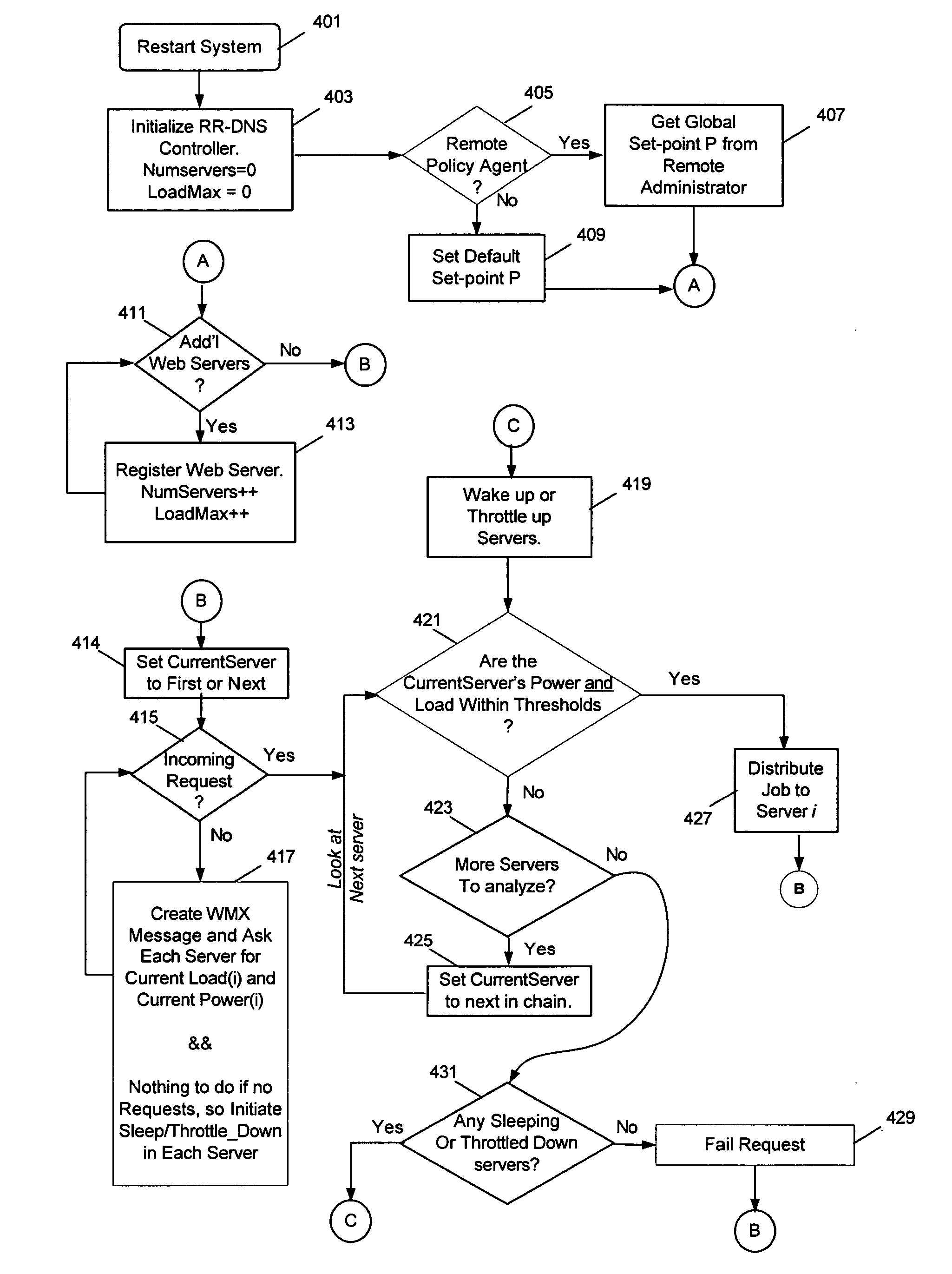
[0011] An embodiment of the present invention is a system and method relating to reducing platform power utilization using an enhanced round-robin DNS (herein referred to as “eRR-DNS”) technique. In at least one embodiment, the present invention is intended to balance the work load of network platforms in order to minimize or optimize power utilization.

[0012] Reference in the specification to “one embodiment” or “an embodiment” of the present invention means that a particular feature, structure or characteristic described in connection with the embodiment is included in at least one embodiment of the present invention. Thus, the appearances of the phrase “in one embodiment” appearing in various places throughout the specification are not necessarily all referring to the same embodiment.

[0013] For purposes of explanation, specific configurations and details are set forth in order to provide a thorough understanding of the present invention. However, it will be apparent to one of or...


PUM


Abstract

In some embodiments, the invention involves utilizing an enhanced round robin DNS (eRR-DNS) scheme to maximize throughput while minimizing power consumption in a network of computers. In at least one embodiment, the present invention is intended to balance the work load of network platforms in order to minimize or optimize power utilization. Other embodiments are described and claimed.

Description

FIELD OF THE INVENTION [0001] An embodiment of the present invention relates generally to power utilization in a network of computers and, more specifically, to reducing power utilization using a modified round-robin Domain Name System (DNS) technique. BACKGROUND INFORMATION [0002] Various mechanisms exist for reducing power utilization of a single platform. Power utilization of network systems can be more problematic. In existing systems using multiple platforms to distribute workload, throughput or user connect time are typically the prime concerns of the network load balancer. [0003] A number of domain name system (DNS) servers on the Internet provide translation from commonly used plain text domain names to Internet Protocol (IP) addresses. When a user types in a uniform resource locator (URL) to a web browser, a server (DNS) on the Internet sees this request in hypertext transfer protocol (HTTP) and takes the URL and converts it to an IP address. (Note, to prevent inadvertent h...

Claims


Application Information

Patent Timeline
Patent Type & Authority Applications(United States)
IPC IPC(8): G06F15/173
CPCG06F1/3209H04L29/12066H04L61/1511H04L67/1008H04L67/1002H04L67/1017H04L61/4511H04L67/1001
Inventor ZIMMER, VINCENT J.ROTHMAN, MICHAEL A.
Owner INTEL CORP
Why Eureka
Try Eureka