Dust collecting apparatus for a vacuum cleaner
a technology for vacuum cleaners and dust collecting equipment, which is applied in the direction of vacuum cleaners, vortex flow apparatus, cleaning equipment, etc., can solve the problems of overloading or damaging the suction motor, and the dust collecting apparatus is also problematic, so as to improve the ability to collect moisture
- Summary
- Abstract
- Description
- Claims
- Application Information
AI Technical Summary
Benefits of technology
Problems solved by technology
Method used
Image
Examples
second embodiment
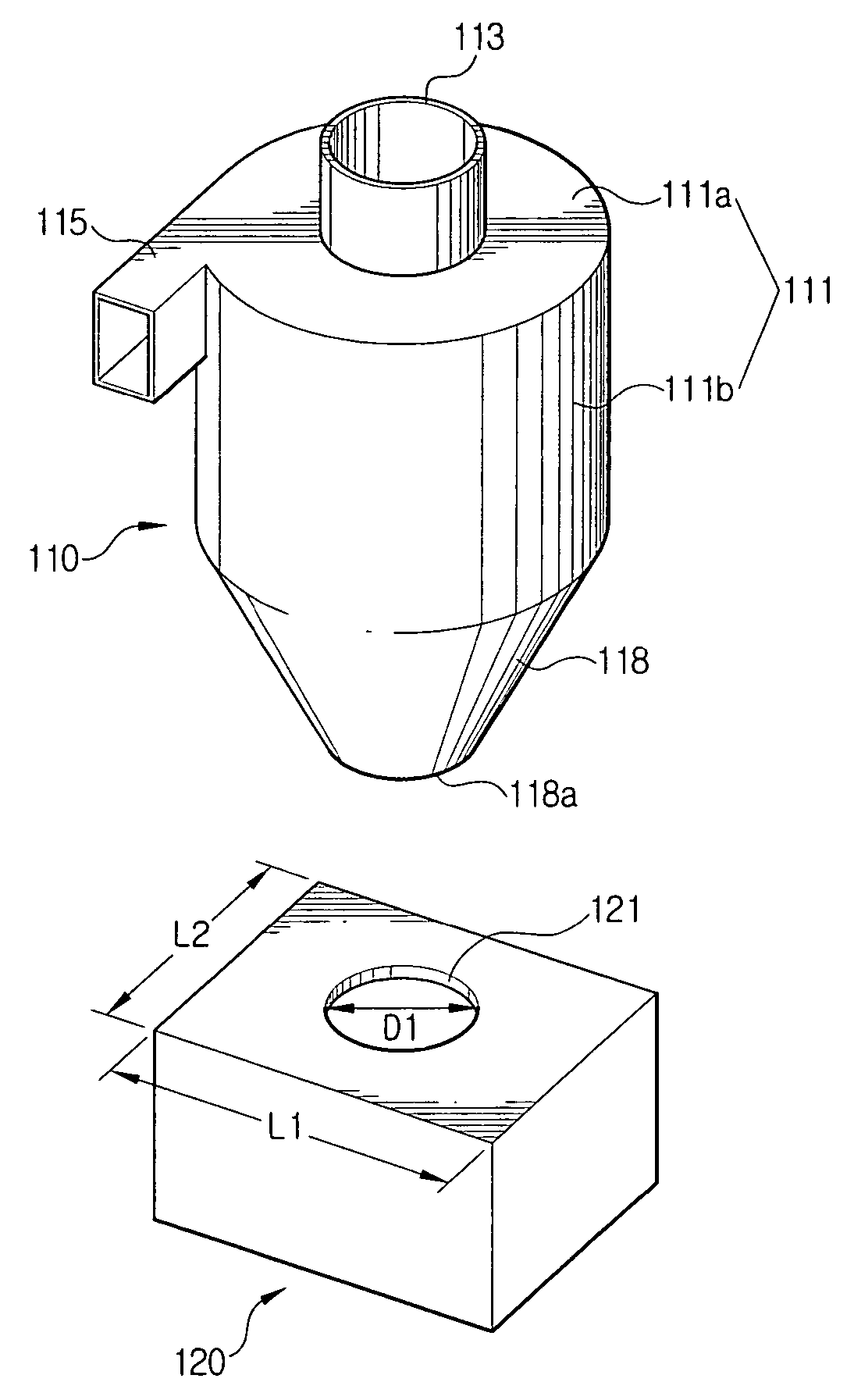
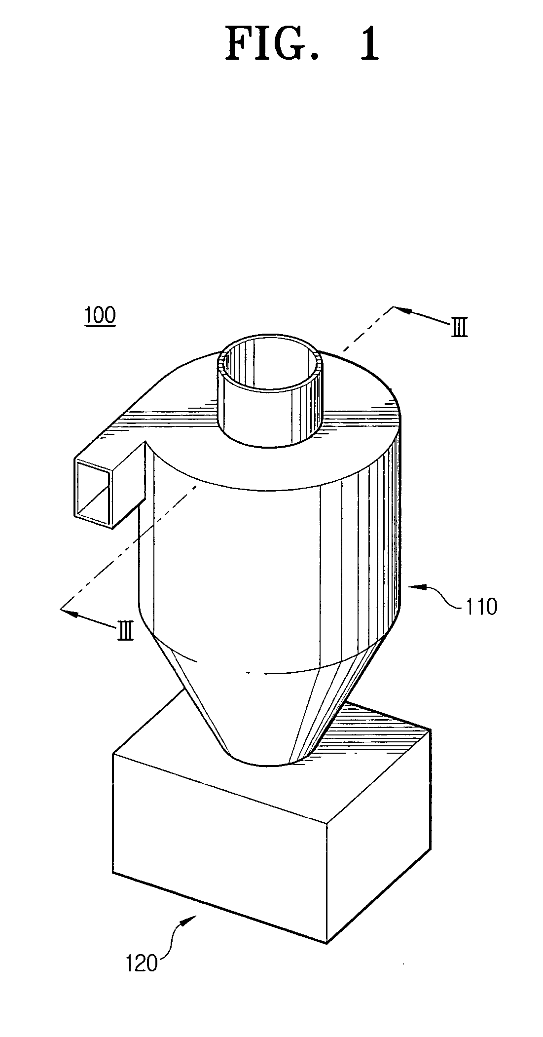
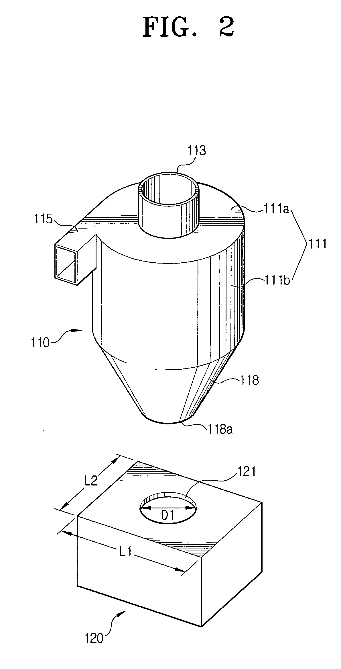
[0034] In order to improve moisture collecting efficiency and prevent the dust and moisture from being mixed with each other in the dust receptacle 120, there is suggested a dust collecting apparatus 200 according to the present invention, as shown in FIGS. 4 to 6.
[0035] Referring to FIGS. 4 to 6, the dust collecting apparatus 200 comprises the cyclone body 110, the dust receptacle 120, a screen 130 (FIG. 6), and a dust-only receptacle 140. With reference to FIGS. 5 and 6, the screen 130 is mounted in the cyclone body 110 and comprises a plurality of moisture passing holes 131a. The screen 130 divides an inside of the cyclone body 110 into first and second spaces S1 and S2. In the first space S1, which communicates with the air inlet 115, the dust and moisture are separated by a centrifugal force. The moisture separated in the first space S1 flows into the second space S2 by passing through the moisture passing holes 131a. Because the moisture is condensed while passing through the ...
fourth embodiment
[0043] Referring to FIGS. 8 and 9, a dust collecting apparatus 400 according to the present invention comprises the cyclone body 110, the screen 130, and a dust receptacle 410. The same elements as in the previous embodiments will be cited by the same reference numerals, omitting detailed description thereof.
[0044] The inside of the cyclone body 110 is partitioned by the screen 130 into the first space S1 wherein the dust is separated and the second space S2 wherein the moisture is separated. A lower end of the cyclone body 110 is open and connected to the dust receptacle 410. The dust and moisture separated in the first and the second spaces S1 and S2, respectively, fall and collect in the dust receptacle 410. In order to prevent the moisture collected in the dust receptacle 410 from flowing back into the first and the second spaces S1 and S2, the screen 130 is provided with the screen cylindrical part 131 corresponding to the cylindrical part 111 of the cyclone body 110, the scree...
third embodiment
[0046] Additionally, as mentioned regarding the third embodiment, the electric heating coil 150 may be provided in the air inlet 515 of the dust collecting apparatus 500.
[0047] As described above, with the dust collecting apparatuses 100, 200, 300, 400, and 500 according to the present invention, because the moisture collected by the taper part is restrained from flowing back to a filter, blocking of the filter due to the moisture can be prevented. Accordingly, a uniform suction force of the vacuum cleaner can be maintained, without causing overload of the suction motor.
[0048] Furthermore, the screen improves the moisture separation efficiency. Therefore, the filter of the vacuum cleaner will not be easily blocked by unseparated moisture. As a result, the vacuum cleaner operates with uniform suction force, and the suction motor is not overloaded.
PUM
| Property | Measurement | Unit |
|---|---|---|
| Fraction | aaaaa | aaaaa |
| Fraction | aaaaa | aaaaa |
| Diameter | aaaaa | aaaaa |
Abstract
Description
Claims
Application Information
 - R&D
- Intellectual Property
- Life Sciences
- Materials
- Tech Scout
- Unparalleled Data Quality
- Higher Quality Content
- 60% Fewer Hallucinations
Browse by: Latest US Patents, China's latest patents, Technical Efficacy Thesaurus, Application Domain, Technology Topic, Popular Technical Reports.
© 2025 PatSnap. All rights reserved.Legal|Privacy policy|Modern Slavery Act Transparency Statement|Sitemap|About US| Contact US: help@patsnap.com


