
Hydrogen production from an integrated electrolysis cell and hydrocarbon gasification reactor

Active Publication Date: 2013-12-19
SAUDI ARABIAN OIL CO
View PDF16 Cites 61 Cited by
  • Summary
  • Abstract
  • Description
  • Claims
  • Application Information

AI Technical Summary

Benefits of technology

The patent describes a process and apparatus for making hydrogen gas through a water-gas shift reaction. This reaction converts CO gas into CO2 gas and increases the amount of hydrogen in the gas. The technical effect of this process is an improved method for producing hydrogen gas with a higher concentration of hydrogen.

Problems solved by technology

However, the gasification reactor 104 has a relatively limited lifetime that can be as short as from 3 to 18 months, depending upon the characteristics of the feed and the design of the unit.
The replacement of refractory linings can cost several millions of dollars a year and several weeks of downtime for a given reactor.
Up until now, the solution has been the installation of a second or parallel gasifier to provide the necessary continuous operating capability, but the undesirable consequence of this duplication is a significant increase in the capital costs associated with the unit operation.
Both systems have demonstrated high utility with solid fuels, but not with liquid fuels.
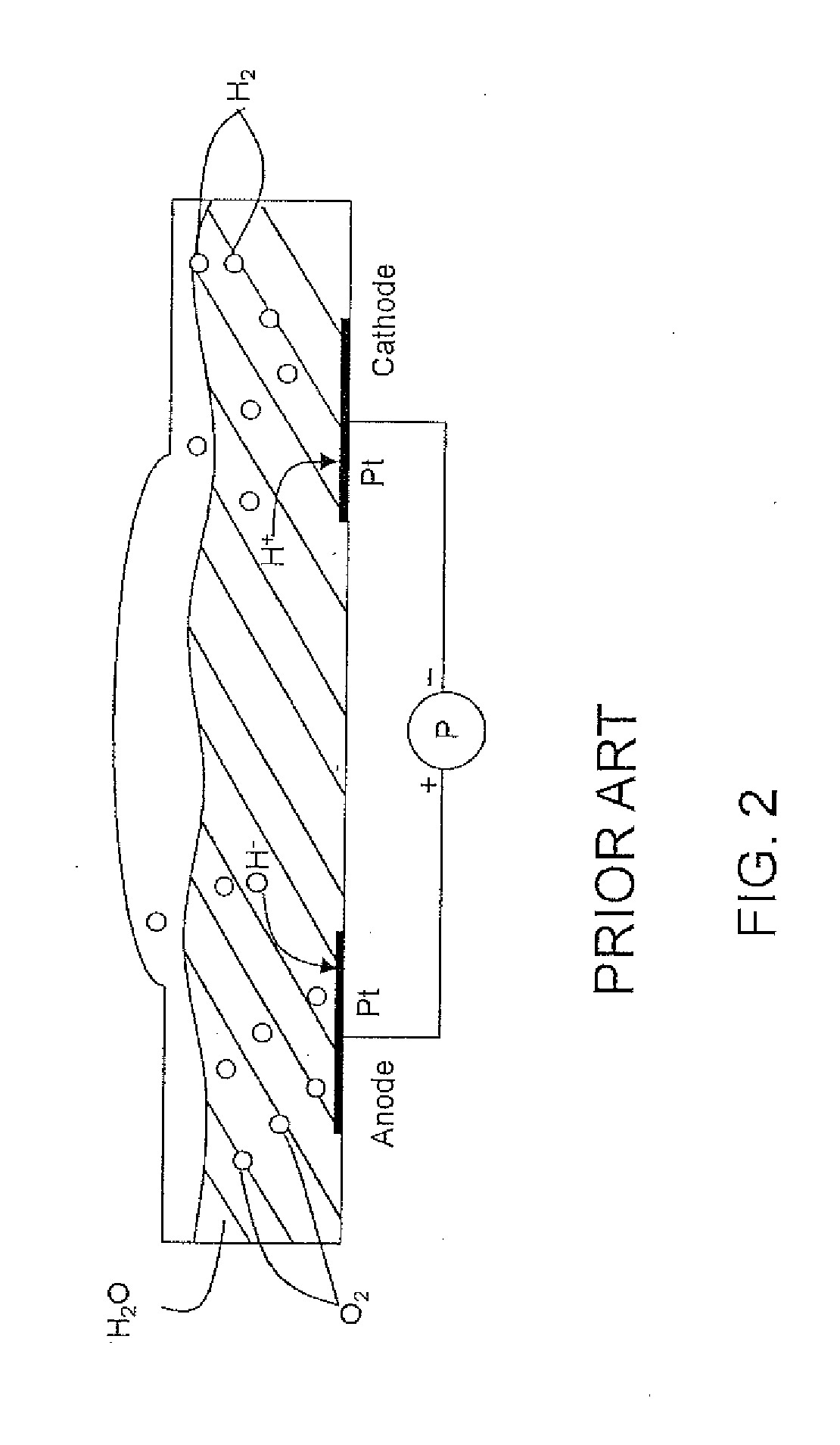
Because of its high energy consumption and substantial capital investment, water electrolysis is currently used for only 4% of world hydrogen production.
While both the gasification and water electrolysis processes are well developed and suitable for their intended purposes, their combination and applications in conjunction with upgrading crude oil and its fractions do not appear to have been developed.

Method used


Image

  • Hydrogen production from an integrated electrolysis cell and hydrocarbon gasification reactor
  • Hydrogen production from an integrated electrolysis cell and hydrocarbon gasification reactor
  • Hydrogen production from an integrated electrolysis cell and hydrocarbon gasification reactor

Examples


example

[0084]The apparatus described in FIG. 7 is used to illustrate the present invention. A one hundred thousand barrels per day (KBPD) of Arab light crude oil, the properties of which are shown in Table 2 below, was introduced as a feedstock into an ADU and the atmospheric residue passed to a VDU.

TABLE 2Properties of Arab Light Crude OilNameCrude OilSG0.869API Gravity31.4Sulfur, W %1.94Nitrogen, ppmw842MCR, W %5.36C5-Asphalthenes, W %2.45Ni, ppmw5V, ppmw17

[0085]The distillates and vacuum gas oil fractions were obtained from the crude oil and passed to the respective hydrotreating and hydrocracking units to remove the impurities. The vacuum residue fraction was sent to the Electrolysis Gasification Island to produce hydrogen needed for the hydrotreating and hydrocracking steps. Material balances are given in Table 3. The stream numbers referred to in Table 3 correspond to the streams in FIG. 7.

TABLE 3Material BalanceStreamStream #Flow, Kg / hCrude Oil1 331,442Distillates2a184,945Hydrotreat...


PUM


Abstract

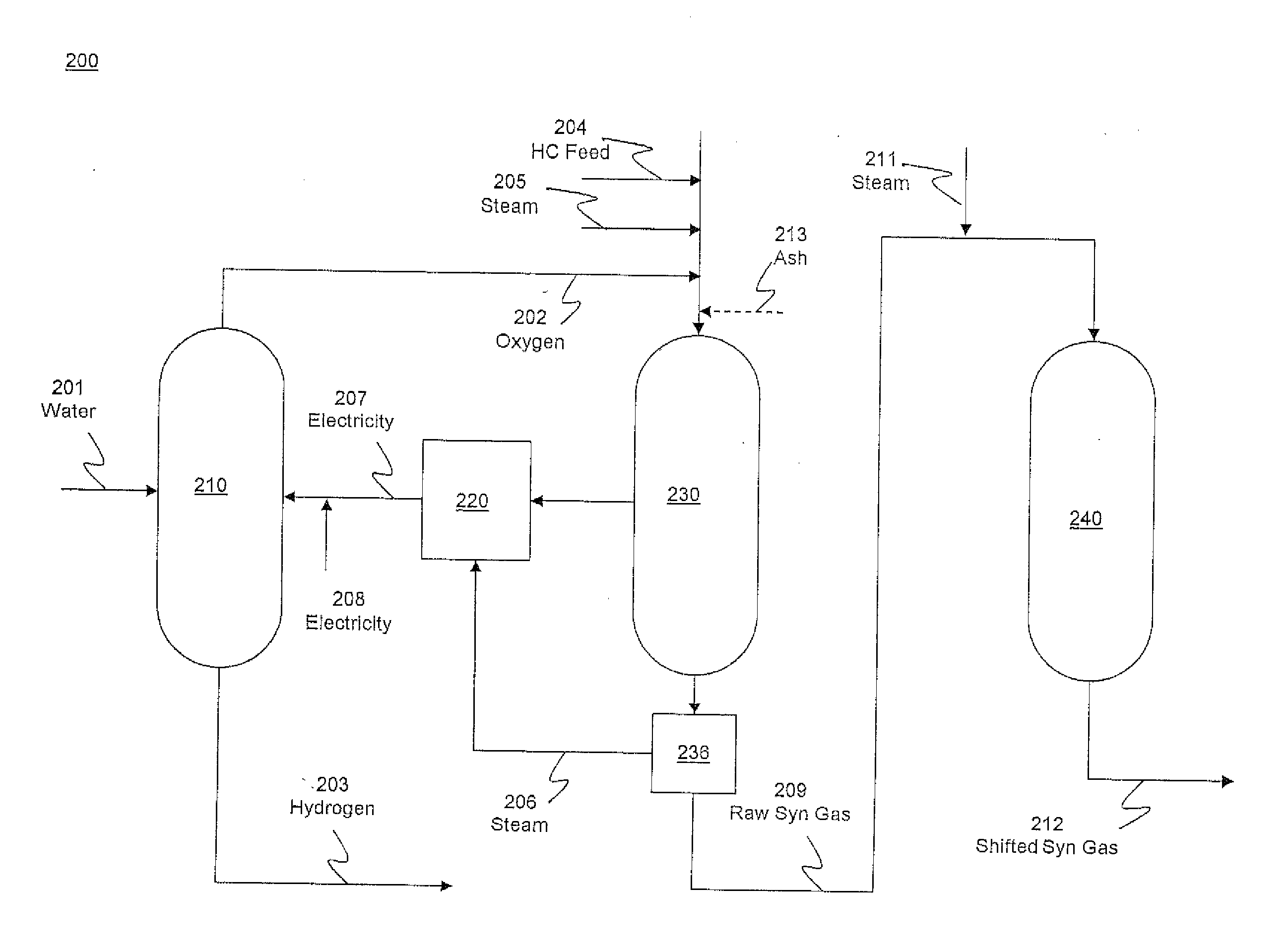
An integrated process for hydrogen gas production includes:a. operating a water electrolysis cell with an external source of electricity to produce oxygen and hydrogen;b. optionally operating an air separation unit to produce additional oxygen for the process;c. introducing a hydrocarbon feedstock into a membrane wall gasification reactor with an ash-forming material and steam, and oxygen from the electrolysis cell and, optionally, oxygen from the air separation unit to produce hot raw synthesis gas;d. passing the hot raw synthesis gas from the gasification reactor to a steam-generating heat exchanger to produce steam and a cooled raw synthesis gas;e. introducing the steam generated in the heat exchanger into a turbine to produce electricity to operate the electrolysis cell; andf. recovering the hydrogen gas from the water electrolysis cell and, optionally, subjecting the synthesis gas to a water-gas shift reaction to increase the hydrogen content and recovering the hydrogen.

Description

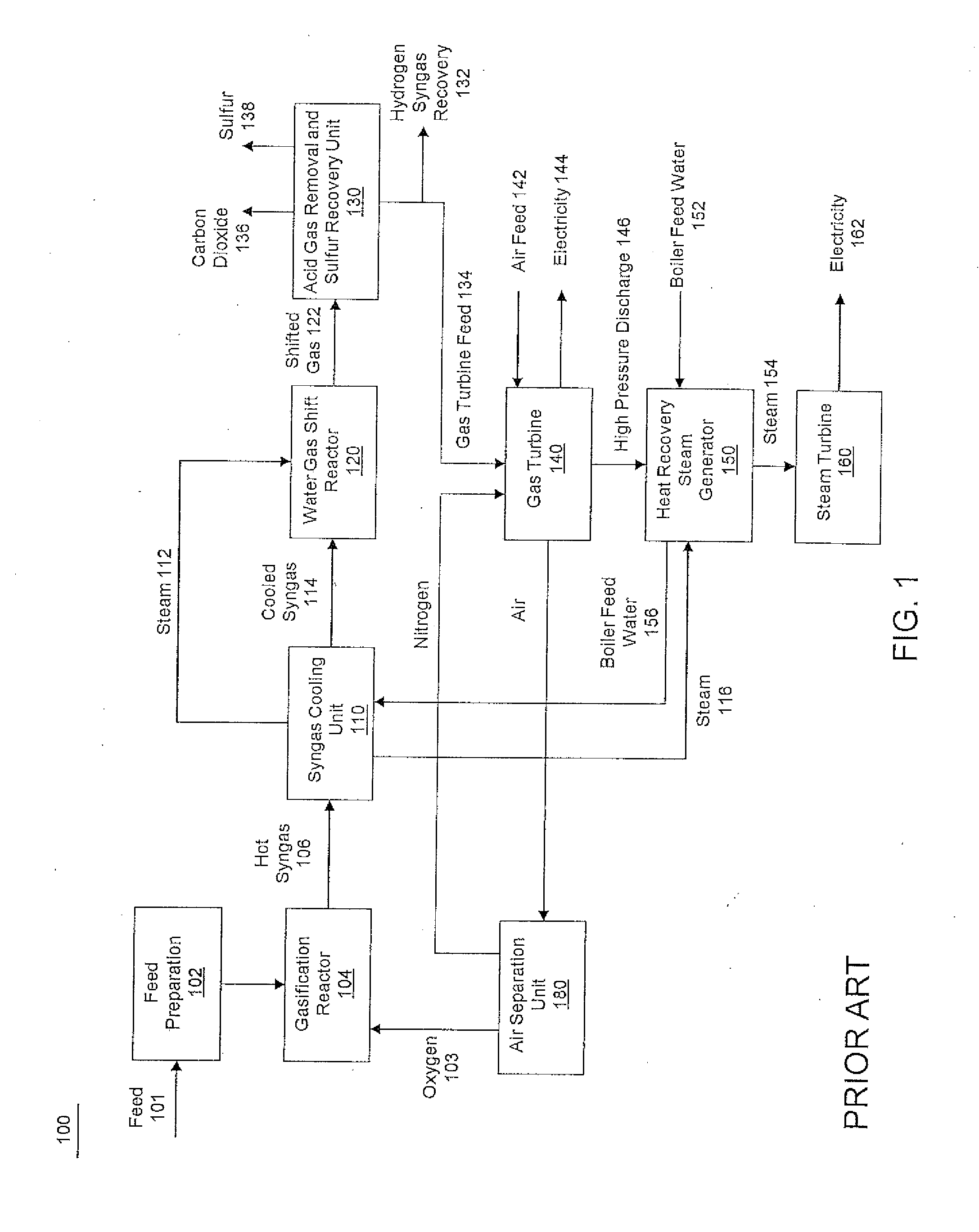
RELATED APPLICATIONS[0001]This application claims priority to provisional patent application U.S. Ser. No. 61 / 659,206 filed Jun. 13, 2012, the contents of which are incorporated herein by reference.BACKGROUND OF THE INVENTION[0002]1. Field of the Invention[0003]The present invention relates to processes for the production of hydrogen from an integrated water electrolysis cell and hydrocarbon gasification reactor.[0004]2. Description of Related Art[0005]Gasification is well known in the art and it is practiced worldwide with application to solid and heavy liquid fossil fuels, including refinery bottoms. The gasification process uses partial oxidation to convert carbonaceous materials, such as coal, petroleum, biofuel, biomass and other hydrocarbon-containing materials with oxygen at high temperature, i.e., greater than 800° C., into a synthesis gas (“syngas”), steam and electricity. The syngas consists of carbon monoxide and hydrogen and can be burned directly in internal combustion ...

Claims


Application Information

Patent Timeline
IPC IPC(8): C25B1/10
CPCC25B1/10C10J3/485C10K3/04C25B1/04Y02P20/132Y02E60/366Y02E20/18C10G49/007Y02P20/125C10J2300/1684Y02E60/36Y02P20/10C25B9/73Y02P20/129
Inventor KOSEOGLU, OMER REFABALLAGUET, JEAN PIERRE
Owner SAUDI ARABIAN OIL CO
Learn More