
Low power nitrogen enriched air generation system

a nitrogen-enriched air and generation system technology, applied in the field of low-power nitrogen-enriched air generation system, can solve problems such as substantial weight, and achieve the effect of optimizing oxygen reduction in gas used and capacity and weight reduction

Inactive Publication Date: 2005-07-05
HAMILTON SUNDSTRAND CORP
View PDF59 Cites 62 Cited by
  • Summary
  • Abstract
  • Description
  • Claims
  • Application Information

AI Technical Summary

Benefits of technology

[0005]An embodiment of this invention is an inerting system for reducing the oxygen content within an air stream including a second compressor driven by exhaust to increase air pressure to optimal working pressure of an air separation module.
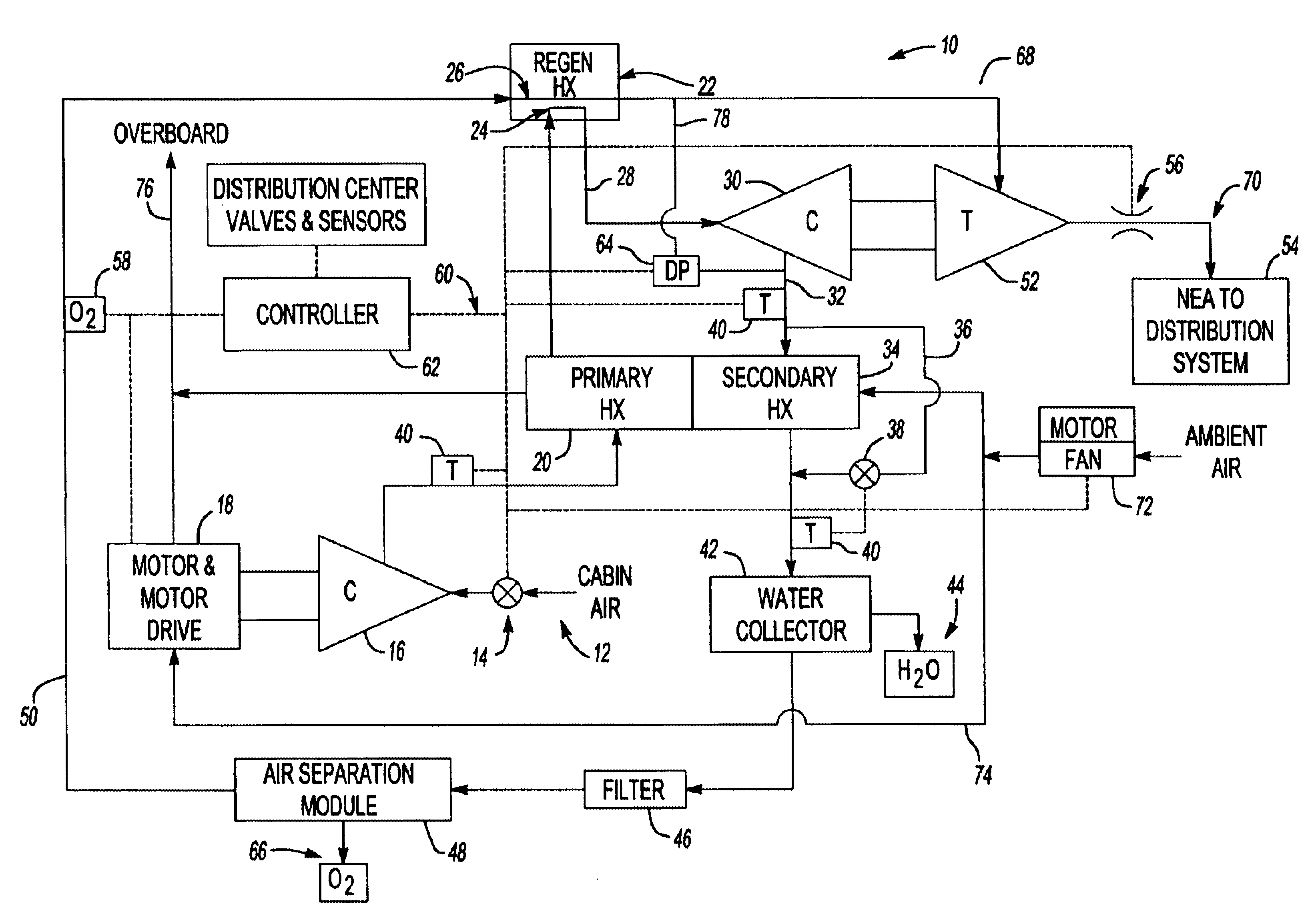
[0008]Air exhausting from the second compressor is at the optimal working pressure for the air separation module. Air enters the air separation module and oxygen is substantially reduced or eliminated from the air stream. Air exiting the air separation module is then routed to the turbine that drives the second compressor. The pressure of air exiting the air separation module and driving the turbine is at a pressure much higher than that required by the fuel distribution system. Therefore, the excess energy available within the high-pressure air is used to drive the second compressor. Driving the second compressor with the energy provided in the high-pressure air utilizes energy that would otherwise simply be exhausted to atmosphere to allow a substantial reduction in capacity and weight of the first compressor that in turn provides an overall weight and size reduction of the inerting system.
[0009]Accordingly, the inerting system of this invention provides a compact and lightweight system by utilizing excess energy input into the system to drive a second compressor to optimize oxygen reduction in gases used to inert fuel tanks.

Problems solved by technology

The compressor and motor to drive the compressor contribute a substantial amount of weight to an aircraft.

Method used


Image

  • Low power nitrogen enriched air generation system
  • Low power nitrogen enriched air generation system

Examples


Embodiment Construction

[0011]Referring to FIG. 1, an embodiment of this invention is an inerting system generally indicated at 10. The inerting system 10 includes an air separation module 48 to remove oxygen from air drawn from the cabin of the aircraft as indicated at 12. The air separation module 48 operates most efficiently to remove oxygen from air at an optimal working pressure. To obtain the optimal working pressure a first compressor 16 is provided. The first compressor 16 provided is driven by a motor 18. The motor 18 and compressor 16 are of a size and capacity to only elevate air pressure a portion of the required working pressure.

[0012]A second compressor 30 powered by a turbine 52 used air pressure exiting the inerting system through the outlet 70. Air exiting the outlet 70 to the fuel distribution system 54 is only required to be at a pressure matching that of the conditions within the fuel distribution system. The pressure required within the fuel distribution system 54 is much lower than th...


PUM

PropertyMeasurementUnit
Temperatureaaaaaaaaaa
Pressureaaaaaaaaaa
Contentaaaaaaaaaa

Abstract

An inerting system provides air with reduced oxygen content by flowing and directing air through an air separation module. Optimal working pressure for the air separation module is obtained with two compressors. A first compressor elevates air from the aircraft cabin to a second pressure. The second pressure is at an intermediate level below the working pressure of the air separation module. A second compressor elevates air from the second pressure to the working pressure. The second compressor is driven by air that is exhausted through a turbine. The pressure difference between air at the working pressure and air required by the fuel distribution system is used to power the turbine and drive the second compressor.

Description

BACKGROUND OF THE INVENTION[0001]The present invention generally relates to a method and system for inerting aircraft fuel tanks by providing a nitrogen enriched air supply, and specifically to a system for increasing working air pressures to optimize efficiency of an air separation module by using exhaust gases to power a second compressor.[0002]It is recognized that fuel vapors created within fuel tanks become combustible in the presence of oxygen. The possibility of explosion or fire can be substantially reduced by reducing or eliminating the amount of oxygen present within the fuel tank. It is known in the art to equip aircraft with onboard inert gas generating systems. The inert gas generating system supplies nitrogen enriched air to the vapor space within the fuel tank. The nitrogen-enriched air has a substantially reduced oxygen content that reduces or eliminates combustible conditions within the fuel tank.[0003]Typically, the inert gas generating system includes a compressor...

Claims


Application Information

Patent Timeline
IPC IPC(8): A62B7/00A62B7/14B64D37/32B64D37/00F01D15/08F02C1/02F02C7/25
CPCA62B7/14B64D37/32B64D2013/0677Y02T50/44Y02T50/40
Inventor DEFRANCESCO, GREGORYZYWIAK, THOMASHIPSKY, HAROLD W.
Owner HAMILTON SUNDSTRAND CORP
Learn More