Illumination devices and methods of making the same

a technology of illumination device and self-powered technology, which is applied in the direction of lighting and heating apparatus, greenhouse gas reduction, and power with built-in capacity, can solve the problems of difficult design and manufacturing of such devices, high cost of wiring from an electric power station to a desired location, and difficulty in integrating devices for converting solar energy to electric power and storing the generated electric power

Inactive Publication Date: 2006-06-22
GENERAL ELECTRIC CO
View PDF6 Cites 82 Cited by
  • Summary
  • Abstract
  • Description
  • Claims
  • Application Information

AI Technical Summary

Problems solved by technology

Typically, such devices are useful for applications where sufficient electric power is not available or the cost of wiring from an electric power station to a desired location is substantially high.
However, designing and manufacturing such devices is difficult due to challenges in fabrication and integration of components.
Incorporation of functionalities to manage the color and appearances of such devices is a challenge due to costs and functionality issues.
Further, integration of devices for converting the solar energy to electric power and for storing the generated electric power is difficult due to the challenges in the existing device fabrication process.

Method used


Image

  • Illumination devices and methods of making the same
  • Illumination devices and methods of making the same
  • Illumination devices and methods of making the same

Examples


Embodiment Construction

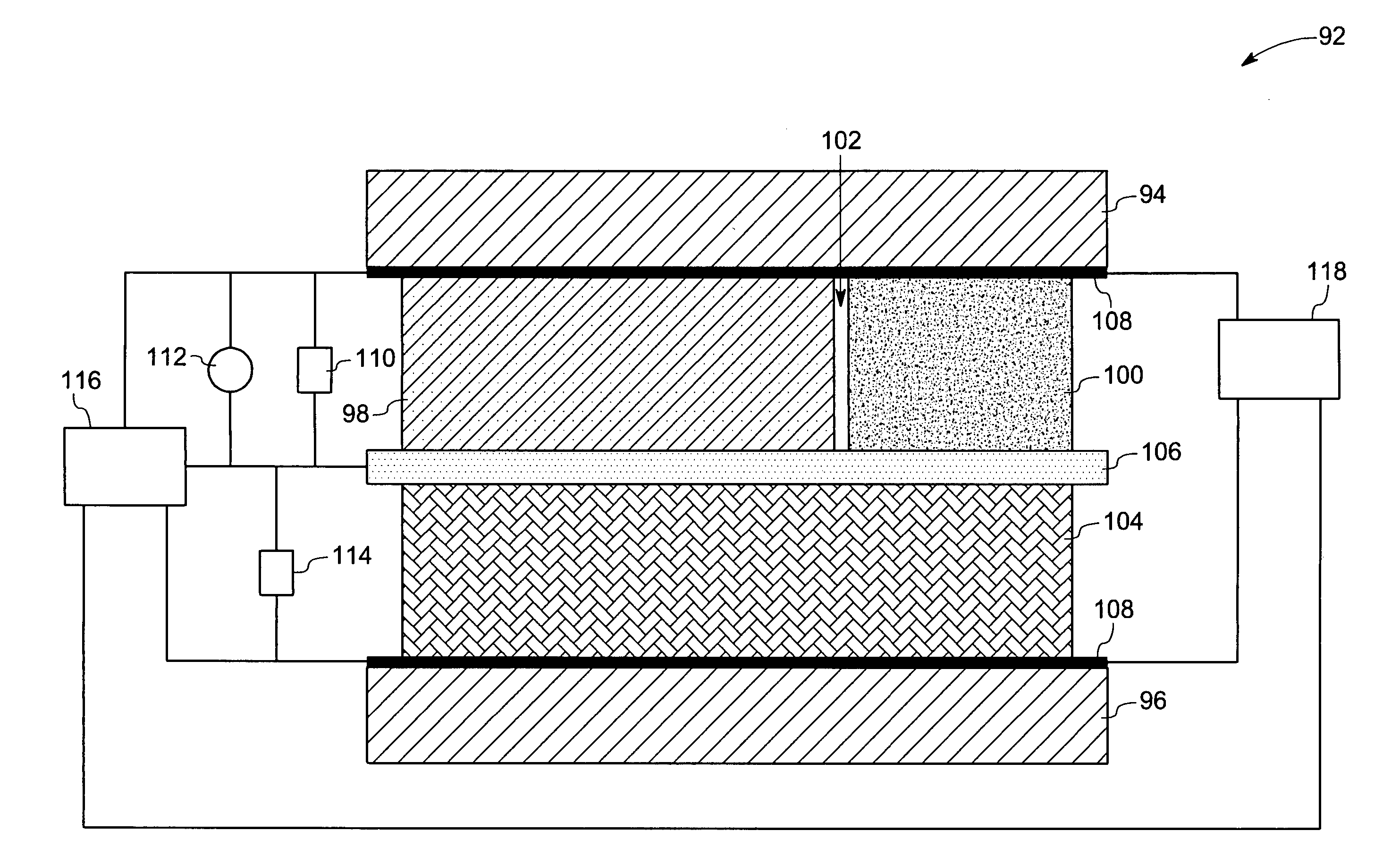
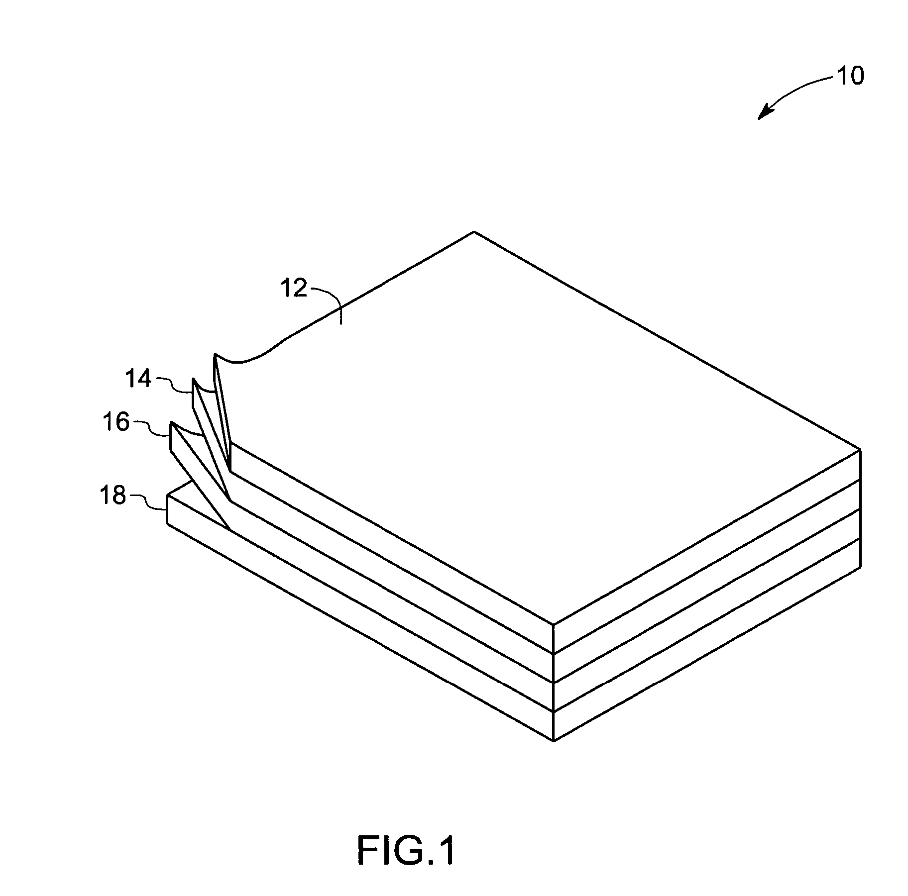
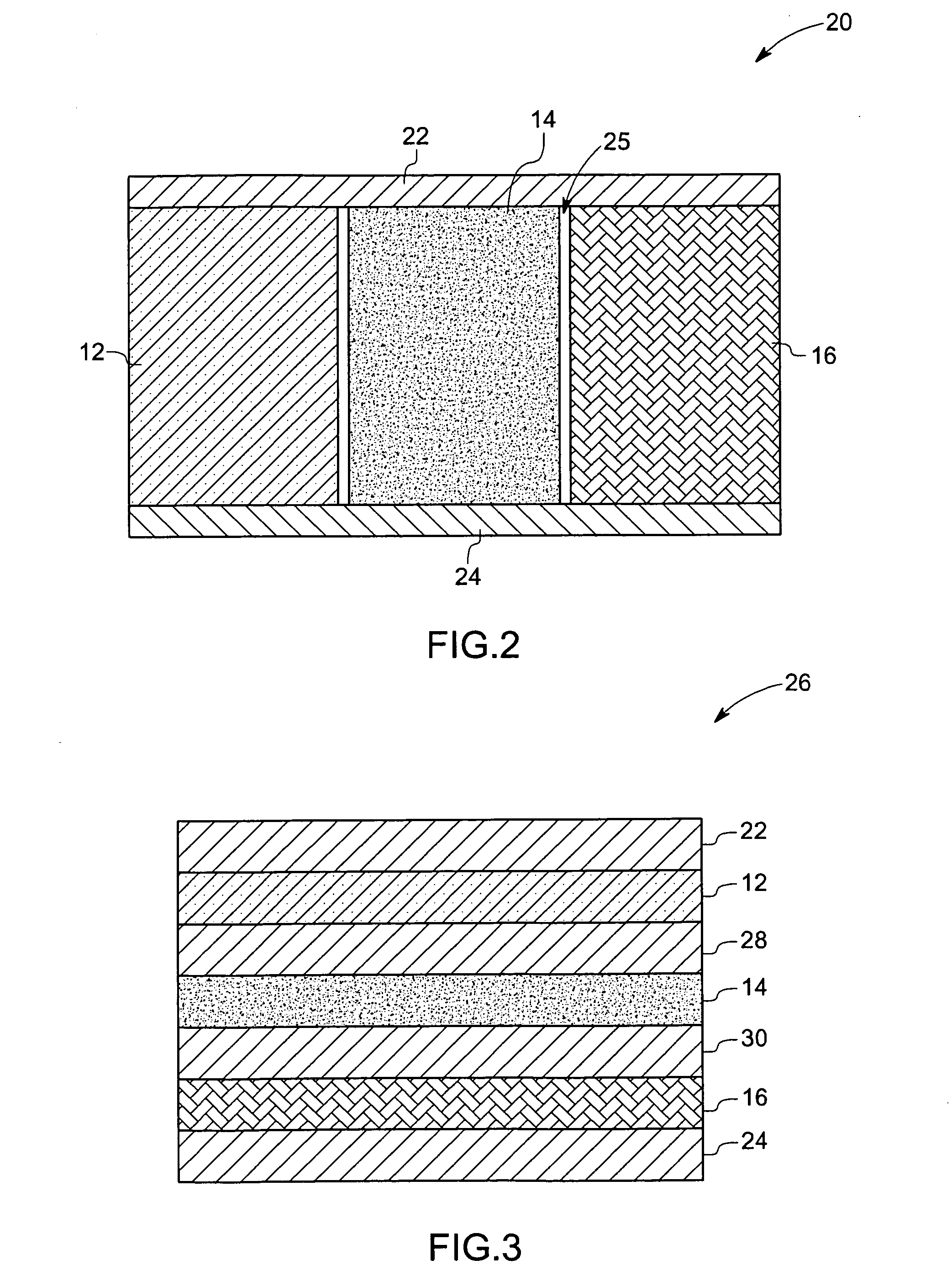
[0017] As further described below, a number of alternate embodiments for an illumination device in accordance with the present techniques are provided. Each illumination device includes a photovoltaic device, such as an organic photovoltaic element (OPV), an electroluminescence element, such as an organic light emitting device (OLED) and a storage element, such as a battery or capacitor. The elements are coupled between electrodes to form the illumination device. As will be appreciated, each of the elements may be contained within a single layer (i.e. between a top electrode and a bottom electrode). Alternatively, the illumination device may further include one or two additional substrates between the outer electrodes, such that the elements are contained within two or three layers. Regardless of the particular configuration, each of the present embodiments includes at least one organic element and at least one flexible substrate, as described further below.

[0018] Referring now to ...


PUM


Abstract

An illumination device includes a photovoltaic element, wherein the photovoltaic element is configured to absorb photons of desired wavelengths and to convert the absorbed photon energy to electric energy and an electroluminescence element disposed adjacent to the photovoltaic element, wherein the electroluminescence element is configured to produce illumination at desired wavelengths, and wherein at least one of the photovoltaic element or the electroluminescence element comprises an organic device. The illumination device also includes an electric energy storage element coupled to the photovoltaic element and to the electroluminescence element, wherein the electric energy storage element is configured to store electric energy from the photovoltaic element and to power the electroluminescence element. The illumination device includes a first and second substrate, wherein each of the photovoltaic element, the electroluminescence element and the electric energy storage element are located between the first and second substrates and wherein at least one of the first or second substrate comprises a flexible substrate. The illumination device further comprises sensor controlled electronics coupled to the device, wherein the sensor controlled electronics is configured to control the operation of the organic photovoltaic element, the electroluminescence element and the electric energy storage element.

Description

BACKGROUND [0001] The invention relates generally to illumination devices, and more particularly, to flexible self-powered illumination devices that are configured to convert photon energy to electric energy for providing illumination. [0002] Various illumination devices that utilize solar energy for illumination are known and are generally in use. Typically, such devices are useful for applications where sufficient electric power is not available or the cost of wiring from an electric power station to a desired location is substantially high. In certain applications, a solar cell and a display device are coupled to provide illumination by converting solar energy to electric power. However, designing and manufacturing such devices is difficult due to challenges in fabrication and integration of components. [0003] Moreover, in certain applications such as, signage, consumer electronics and security sensors it may be desirable to manage and control the color and appearance of such ill...

Claims


Application Information

Patent Timeline
Patent Type & Authority Applications(United States)
IPC IPC(8): H01L31/00
CPCF21S9/037H01L25/046H01L27/288H02S40/38H01L27/305H01L2251/5361H01L27/301H01L2924/0002Y02E10/50Y02E70/30H10K19/901H10K65/00H10K39/30H10K39/10H01L2924/00
Inventor GUI, JOHN YUPENGDUGGAL, ANIL RAJPOPIELARCZYK, JEFFREY JOSEPH
Owner GENERAL ELECTRIC CO
Why Eureka
Try Eureka