Flow control apparatus for use in a wellbore

a flow control and wellbore technology, applied in the direction of wellbore/well accessories, fluid removal, construction, etc., can solve the problems of inability to measure production, inconvenient operation, and inability to control the flow of fluid into the wellbor

Active Publication Date: 2006-06-22
WEATHERFORD TECH HLDG LLC
View PDF14 Cites 124 Cited by
  • Summary
  • Abstract
  • Description
  • Claims
  • Application Information

AI Technical Summary

Benefits of technology

[0007] The present invention provides an apparatus for use in a hydrocarbon producing wellbore to prevent the introduction into the wellbore of gas and / or water when the gas or water is of a given percentage relative to the overall fluid content of the production. In one aspect of the invention, a perforated inner tube is surrounded by at least one axially movable member that moves in relation to a pressure differential between sides of a piston having at least one sized orifice through which the production flows to enter the wellbore. The movable member selectively exposes and covers the perforations of the inner tube to pass or choke production. In another embodiment, a method is disclosed to choke the flow of production into a wellbore when a predetermined component of the production is made up of gas or water.

Problems solved by technology

Even with exact drilling techniques, the migration of gas and water towards the oil formation and the wellbore is inevitable due to pressure drops caused by the collection and travel of fluid in the wellbore.
The gas and water must be separated at the surface and once the flow of gas begins it typically increases to a point where further production of oil is not cost effective.
However, the devices are not designed to meter production while choking unwanted production components due to its lack of a constantly sized orifice though which to meter the flow of production and determine the relative amounts of gas or water.

Method used


Image

  • Flow control apparatus for use in a wellbore
  • Flow control apparatus for use in a wellbore
  • Flow control apparatus for use in a wellbore

Examples


Embodiment Construction

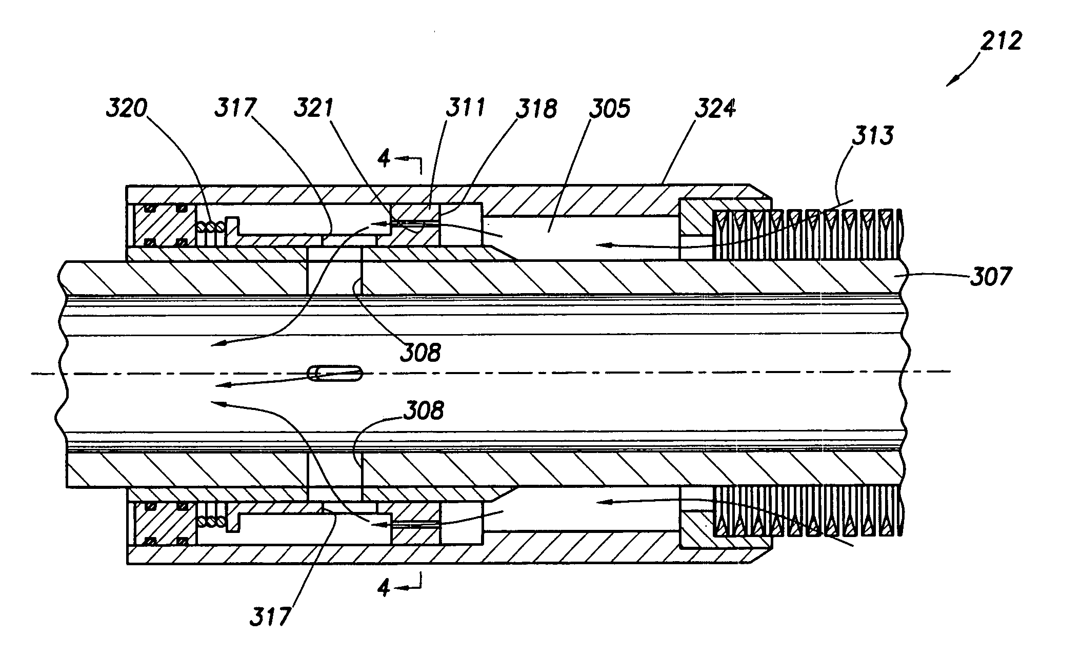
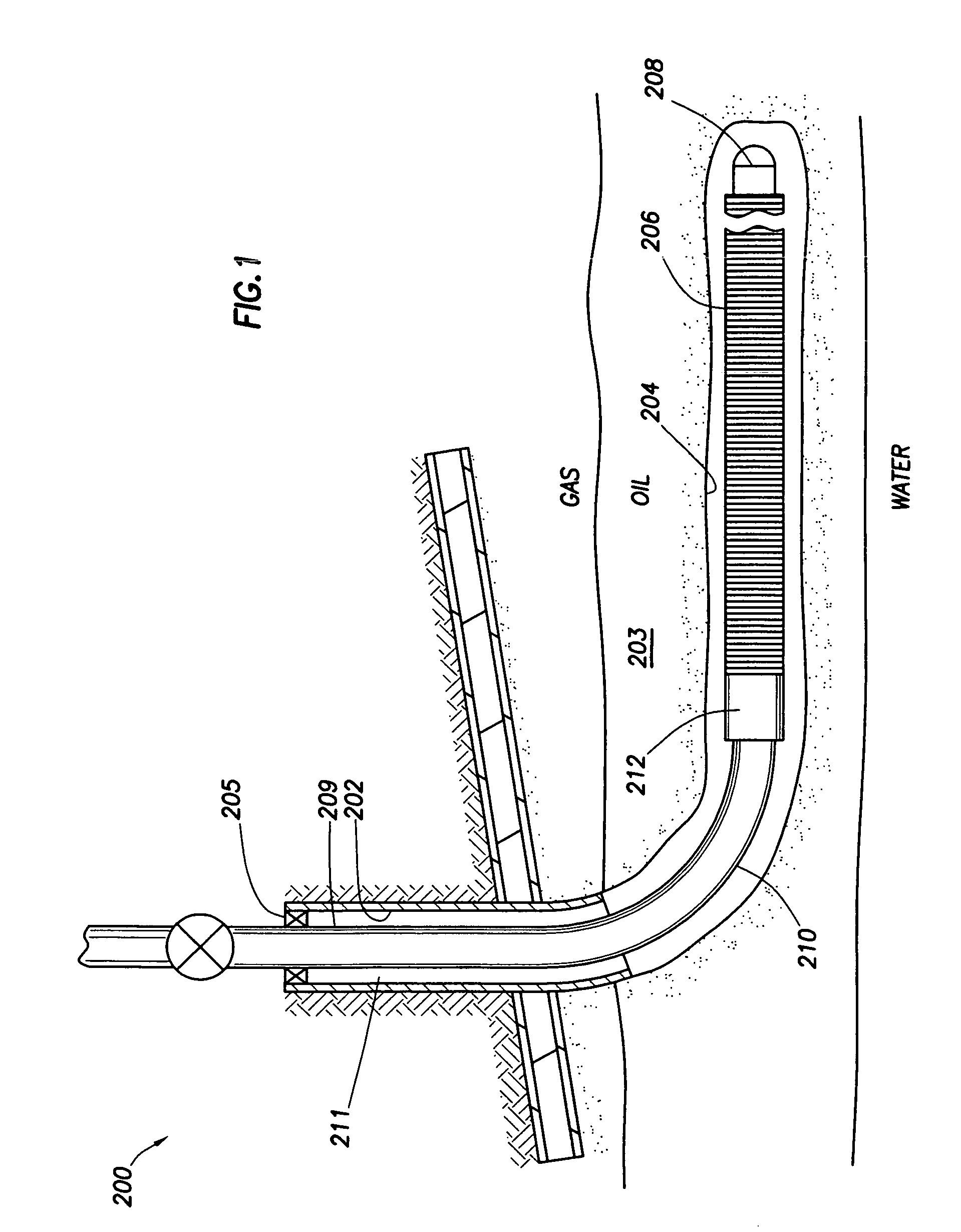
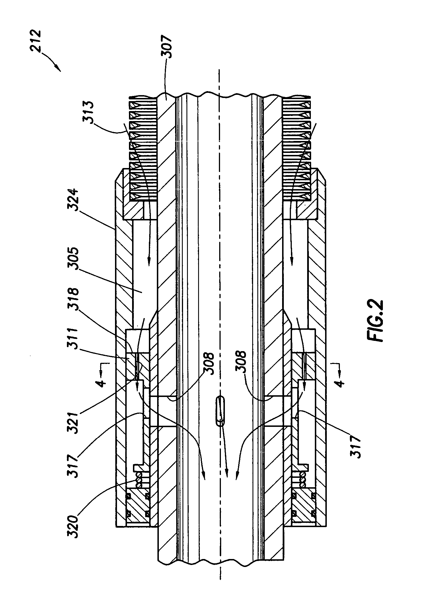
[0014] The present invention is intended to effectively monitor and self adjust the flow of production into a wellbore depending upon the components in the production. To facilitate the description of the invention, the device will typically be described as it would function in the presence of gas and oil in a production stream. However, it will be understood that the invention operates primarily due to differences in densities between oil and another component of production in a wellbore and could operate in the presence of oil and water or any other component having a density distinct from oil. FIG. 1 depicts a cross-sectional view of a well 200 having a flow control apparatus 212 of the present invention located therein. Specifically, an apparatus 212 for controlling the flow of oil or some other hydrocarbon from an underground reservoir 203 through the well 200 is depicted. The well 200 includes a cased, vertical wellbore 202 and an uncased, horizontal wellbore 204. Production t...


PUM


Abstract

Methods and apparatus for use in a wellbore to meter and choke certain components from being produced, based upon their density relative to the density of oil are disclosed. The device includes an inner tubular body portion having apertures in the wall thereof for passing oil, an outer tubular body and at least one metering orifice therebetween to meter production. Disposed around the inner body is an axially movable member to selectively cover and expose the apertures of the inner body, thereby permitting fluid to flow therethrough.

Description

BACKGROUND OF THE INVENTION [0001] 1. Field of the Invention [0002] The invention relates to the control of fluid flow into a wellbore. More particularly, the invention relates to a flow control apparatus that is self adjusting to meter production and choke the flow of gas into the wellbore. [0003] 2. Description of the Related Art [0004] In hydrocarbon wells, horizontal wellbores are formed at a predetermined depth to more completely and effectively reach formations bearing oil or other hydrocarbons in the earth. Typically, a vertical wellbore is formed from the surface of a well and thereafter, using some means of directional drilling like a diverter, the wellbore is extended along a horizontal path. Because the hydrocarbon bearing formations can be hundreds of feet across, these horizontal wellbores are sometimes equipped with long sections of screened tubing which consists of tubing having apertures therethough and covered with screened walls, leaving the interior of the tubing ...

Claims


Application Information

Patent Timeline
Patent Type & Authority Applications(United States)
IPC IPC(8): E21B34/06E21B43/12E21BE21B34/08E21B43/08
CPCE21B34/08E21B43/12E21B43/08
Inventor BODE, JEFFREYFISHBECK, CRAIGLEMBCKE, JEFFREY JOHN
Owner WEATHERFORD TECH HLDG LLC
Why Eureka
Try Eureka