
Cartridge for containing a specimen sample for optical analysis

a specimen sample and optical analysis technology, applied in the direction of immunoassays, chemical methods analysis, material testing goods, etc., can solve the problems of not providing a low cost chamber with uniform analyte distribution for analysis, and the device does not provide for the salvaging of either the test sample or the residue, so as to achieve low cost and avoid loss.

Active Publication Date: 2006-06-01
MENARINI SILICON BIOSYSTEMS SPA
View PDF38 Cites 64 Cited by
  • Summary
  • Abstract
  • Description
  • Claims
  • Application Information

AI Technical Summary

Benefits of technology

"The present invention is an improvement to a cartridge used for optical analysis of specimens. The cartridge has a test chamber that can isolate a small sample for analysis and preserve it for further testing. It also excludes air bubbles and other contaminants from the sample. The cartridge is used in a method for handling specimens that allows the specimen to be presented in a test chamber for optical analysis without any substantial part of it being lost or exposed to other deteriorating conditions. The technical effects of the invention include improved optical analysis, consistent platform for optical analysis, and a low-cost cartridge that can retain the specimen in a safe manner."

Problems solved by technology

Specifically, this collection device enables the exclusion of air as bubbles or other forms from the sample chamber, but does not provide a low cost chamber with uniform analyte distribution for analysis.
The device does not provide for salvaging either of the test sample or the residue and does not have any provision for excluding air in the form of bubbles from the test liquid.
More specifically, interference from adhesive used to join the optically clear land surface with the rest of the cartridge results when the adhesive spreads onto the optical path during the manufacture of the chamber.

Method used


Image

  • Cartridge for containing a specimen sample for optical analysis
  • Cartridge for containing a specimen sample for optical analysis
  • Cartridge for containing a specimen sample for optical analysis

Examples


Embodiment Construction

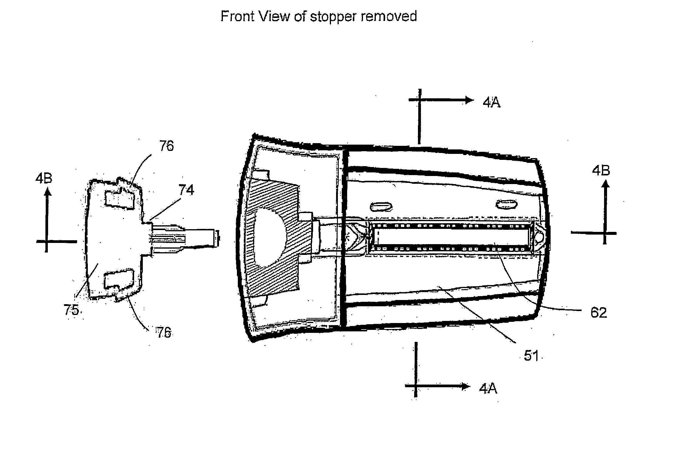
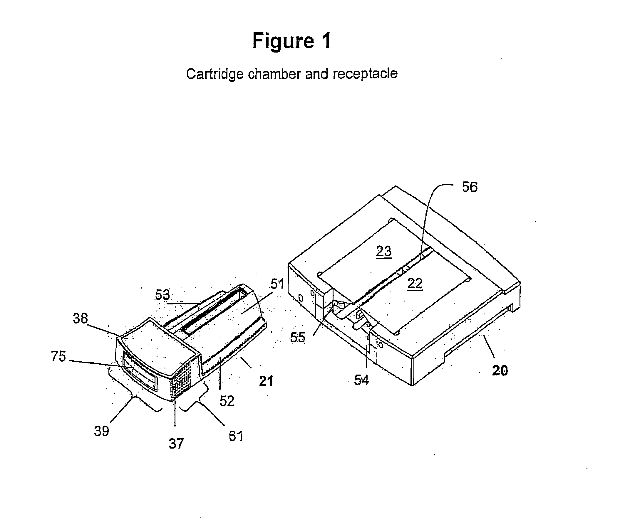
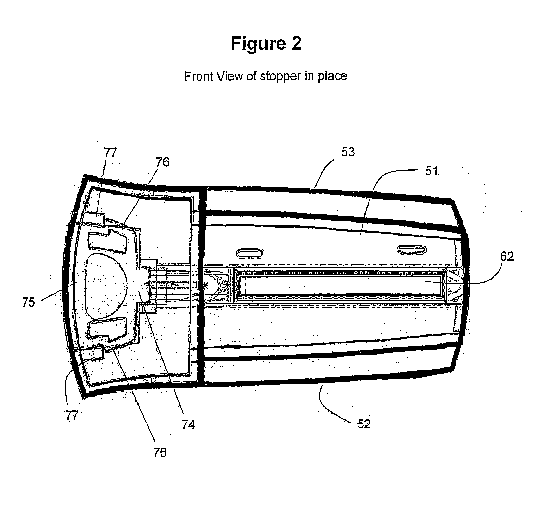
[0019] The device of the present invention has been improved to limit significant settling of target components prior to loading, thus enabling a uniform distribution of the array of magnetically responsive particles and magnetically labeled target components along the viewing surface. Because the biological sample is loaded into the cartridge in the presence of a magnetic field, an equal distribution of magnetically labeled target components is ensured. Loading is accomplished by placing the cartridge vertically within a magnetic field prior to sample loading. The sample is then introduced into the cartridge chamber, closed with a stopper, and maintained until analyzed. Optical analysis is completed without settling and with a uniform distribution of target components that remains consistent from sample to sample.

[0020] As with the cartridge from the parental application, the specimen sample can be introduced into the test chamber of the cartridge along with a buffer solution in w...


PUM

PropertyMeasurementUnit
volumeaaaaaaaaaa
thickaaaaaaaaaa
volumeaaaaaaaaaa

Abstract

An improved cartridge for holding a fluid sample with a small volume is disclosed herein. The cartridge has a test chamber and a vestibule through which the test fluids are inserted into the test chamber. Improved grips are flared-out to aid manipulation. The handle portion is reinforced to prevent flexing, and a prefabricated trough along the edge of the land surface prevents introduction of the adhesive into the region for analysis. The cartridge has a stopper having a dual sealing mechanism, which seals the test chamber inlet between the vestibule and the test chamber, and the mouth of the vestibule so that when the stopper is in place, the test chamber is closed to the admission of air or other contaminants. The vestibule is similarly closed against escape of the overflow from the test chamber. The stopper is composed of a single elastomer. An improved locking mechanism has two flexible walls on either side of the handhold that locks into their respective keepers on the cartridge to provide a secure lock. Additionally, an improved method for loading the cartridge allows for an even distribution of magnetically responsive particles contained within a fluid sample to be viewed in an array through the optically clear land surface portion of the cartridge.

Description

CROSS-REFERENCE TO RELATED APPLICATIONS [0001] This application is a divisional of Ser. No. 10 / 303,309, filed Nov. 25, 2002, now allowed.FIELD OF THE INVENTION [0002] The present invention is an improvement upon an earlier filed application relating to a cartridge having a chamber for containing a specimen sample used in optical analysis (PCT / US02 / 04124; U.S. Pat. No. 6,861,259; U.S. Ser. No. 10 / 988,057). One improvement enables the use of the cartridge in a manner that is more practical and less expensive for analysis of small biological samples, particularly blood. Another improvement enables a more efficient and uniform distribution of magnetically labeled target components within a sample prior to analysis. BACKGROUND OF THE INVENTION [0003] When performing optical analysis on specimens in liquid suspension, it is customary to discard the specimen after analysis. For rare cells, however, it is often desirable to preserve the liquid specimen for further testing or for use in furt...

Claims


Application Information

Patent Timeline
Patent Type & Authority Applications(United States)
IPC IPC(8): B01L9/00B01L3/00G01N21/11G01N35/00
CPCB01L3/508B01L2200/0642B01L2200/0689Y10T436/2575B01L2300/046G01N21/11G01N35/0098B01L2300/042
Inventor KAGAN, MICHAELRAO, GALLA CHANDRAPROHASKA, JERRYALDEN, TOR
Owner MENARINI SILICON BIOSYSTEMS SPA
Learn More