Concave sensor and emitter arrays with integral lens

a concave sensor and emitter array technology, applied in the field of concave sensor and emitter array with integral lens, can solve the problems of cumbersome simultaneous repositioning of image sender display screen, inability to predetermine, and inability to easily detect problems with existing active camouflage schemes, etc., to achieve easy detection, save lives, and light weight

Inactive Publication Date: 2006-06-22
ALDEN RAY M
View PDF1 Cites 7 Cited by
  • Summary
  • Abstract
  • Description
  • Claims
  • Application Information

AI Technical Summary

Benefits of technology

[0009] Accordingly, several objects and advantages of the present invention are apparent. It is an object of the present invention to create a three dimensional virtual image bubble surrounding or on the surface of objects and people. Observers looking at this three dimensional bubble from any viewing perspective are only able to see the background of the object through the bubble. This enables military vehicles and operatives to be more difficult to detect and may save lives in many instances. Likewise, police operatives operating within a bubble can be made difficult to detect by criminal suspects. The apparatus is designed to be rugged, reliable, and light weight.
[0010] The electronic embodiment can alternatively be used as a recording means and a three dimensional display means. The present invention provides a novel means to record visual information and to playback visual information in a three dimensional manor which enables the viewer of the recording to see a different perspective of the recorded light as he moves around the display surfaces while viewing the recorded image.
[0011] Further objects and advantages will become apparent from the enclosed figures and specifications.
[0012]FIG. 1 prior art illustrates the shortcomings of prior art of U.S. Pat. No. 5,220,631 and of U.S. Pat. No. 5,307,162.
[0013]FIG. 2 prior art further illustrates the shortcomings of prior art.
[0014]FIG. 2a prior art is a first observer's perspective of the FIG. 2 objects.

Problems solved by technology

When considering deployment theaters where surroundings are distinctive such as buildings in urban areas, especially where the enemy has familiarity with the locations of background structures, such easily detected problems with the existing active camouflage schemes are not acceptable.
Additionally, when Asset 2 needs to be repositioned, it would be very cumbersome to concurrently reposition the image sender display screen.
Moreover, in today's complex theater conditions it is often not possible to predetermine from which viewing perspective an enemy will be seeing our asset, indeed the enemy may be on all sides of the asset.
In practical application some averaging would occur such that the background reproduction is not perfect.

Method used


Image

  • Concave sensor and emitter arrays with integral lens
  • Concave sensor and emitter arrays with integral lens
  • Concave sensor and emitter arrays with integral lens

Examples


Embodiment Construction

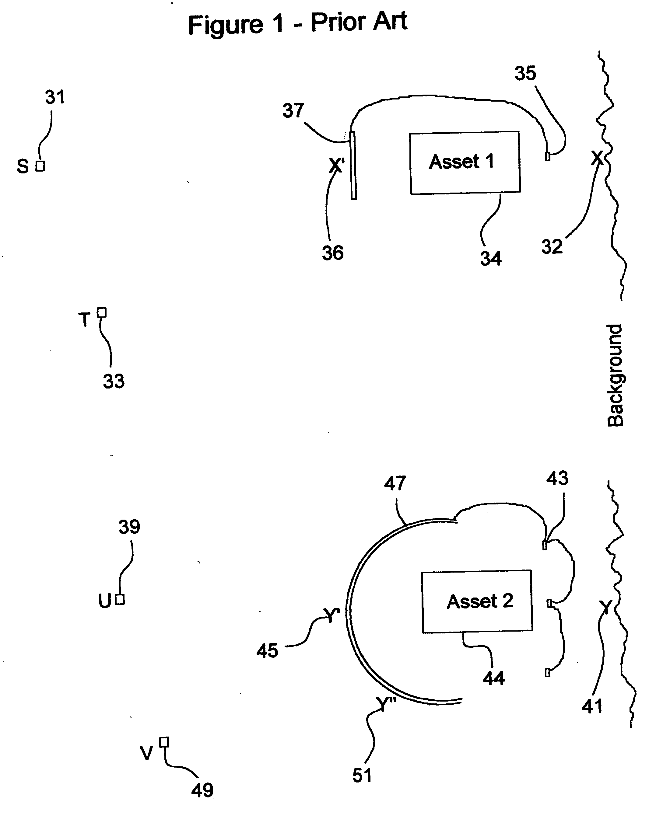
[0026]FIG. 1 prior art, illustrates the shortcomings of prior art of U.S. Pat. No. 5,220,631 and of U.S. Pat. No. 5,307,162. The top half of FIG. 1 illustrates the active camouflage approach used in U.S. Pat. No. 5,220,631. This approach is also described in “JPL New Technology report NPO-20706” August 2000. Asset 134 has a screen or image sender 37 on one side of it. An image receiver 35 on the opposite side of Asset 1 captures an image of the background which is then presented on the image sender. Background point X 32 is represented on the screen as X′36. Note that for an observer at point S 31 this scheme does present a reasonable cloaking apparatus because background points line up with the observer such as X compared with X′. Unfortunately, for observation positions located anywhere other than S, the image sender presents an image that does not correspond with the background. An observer at point T 33 for example can see Asset 1 and can also see back ground point X and backgro...


PUM


Abstract

The invention described herein represents a significant improvement in creating low profile light segmenting devices for cameras, sensors, lighting, and information displays. Photon sensors and/or photon emitters are positioned along the focal curve of a lens so as to efficiently collect light from discrete portions of the background and efficiently emit light into discrete portions of the background. In one embodiment a first emitter such as an LED is positioned at a first focal point on a focal curve, and a second emitter such as an LED is positioned at a second focal point on a focal curve, the focal curve not being flat and being a shape corresponding to the characteristics of an integral lens. In another embodiment a first light receiver such as a photodiode is positioned at a first focal point on a focal curve, and a second light receiver such as a photodiode is positioned at a second focal point on a focal curve, the focal curve not being flat and being a shape corresponding to the characteristics of an integral lens.

Description

CROSS REFERENCE TO RELATED APPLICATIONS [0001] This application is a Continuation-In-Part of Applications including Ser. No. 09 / 757,053 filed Jan. 8, 2001 and Ser. No. 09 / 970,368 filed Nov. 2, 2001.BACKGROUND FIELD OF INVENTION [0002] The field of invention encompasses senor and lens architectures such as prior art cameras wherein a complex lens system is used to focus light from a range of trajectories onto a flat focal back-plane array of sensors. The field of invention also encompasses lighting systems wherein one or more light emitters are arranged in a device to distribute light in a desired distribution pattern such as in prior art headlights and flashlights. The field of invention also encompasses display devices wherein light from individual pixels can vary as a function of an observer's viewing position. The field of the invention being a concave back plane architecture in conjunction with a lens wherein photo-electric sensors and / or electro-photonic emitters are positioned...

Claims


Application Information

Patent Timeline
Patent Type & Authority Applications(United States)
IPC IPC(8): H01L27/00G01J1/04G02B6/06G02B26/06
CPCG02B6/06G02B26/06
Inventor ALDEN, RAY M.
Owner ALDEN RAY M
Why Eureka
Try Eureka