Permanent magnet type motor

a permanent magnet, permanent magnet technology, applied in the direction of dynamo-electric machines, magnetic circuit rotating parts, magnetic circuit shape/form/construction, etc., can solve the problems of increasing the size of the torque linearity, increasing the complexity of the structure, and reducing the cogging torque

Inactive Publication Date: 2006-06-22
MITSUBISHI ELECTRIC CORP
View PDF3 Cites 49 Cited by
  • Summary
  • Abstract
  • Description
  • Claims
  • Application Information

AI Technical Summary

Benefits of technology

[0019] According to the permanent magnet motor in this case, where, for example, the rotor is skewed, the effect of further reducing the cogging torque is obtained.

Problems solved by technology

However, the foregoing surface magnet motor requires the pressing members and associated components for fixing the permanent magnets, resulting in a complicated structure.
However, in the interior permanent magnet in the above described Japanese Laid-Open Patent Publication 197292 / 2000, the thickness of the outer portion of the rotor iron core is not prescribed, so that a problem has been that the cogging torque—the torque variation that when no current is flowing occurs due to harmonic components of the air-gap magnetic flux density—becomes somewhat large, and the torque linearity cannot be improved.

Method used


Image

  • Permanent magnet type motor
  • Permanent magnet type motor
  • Permanent magnet type motor

Examples


embodiment 1

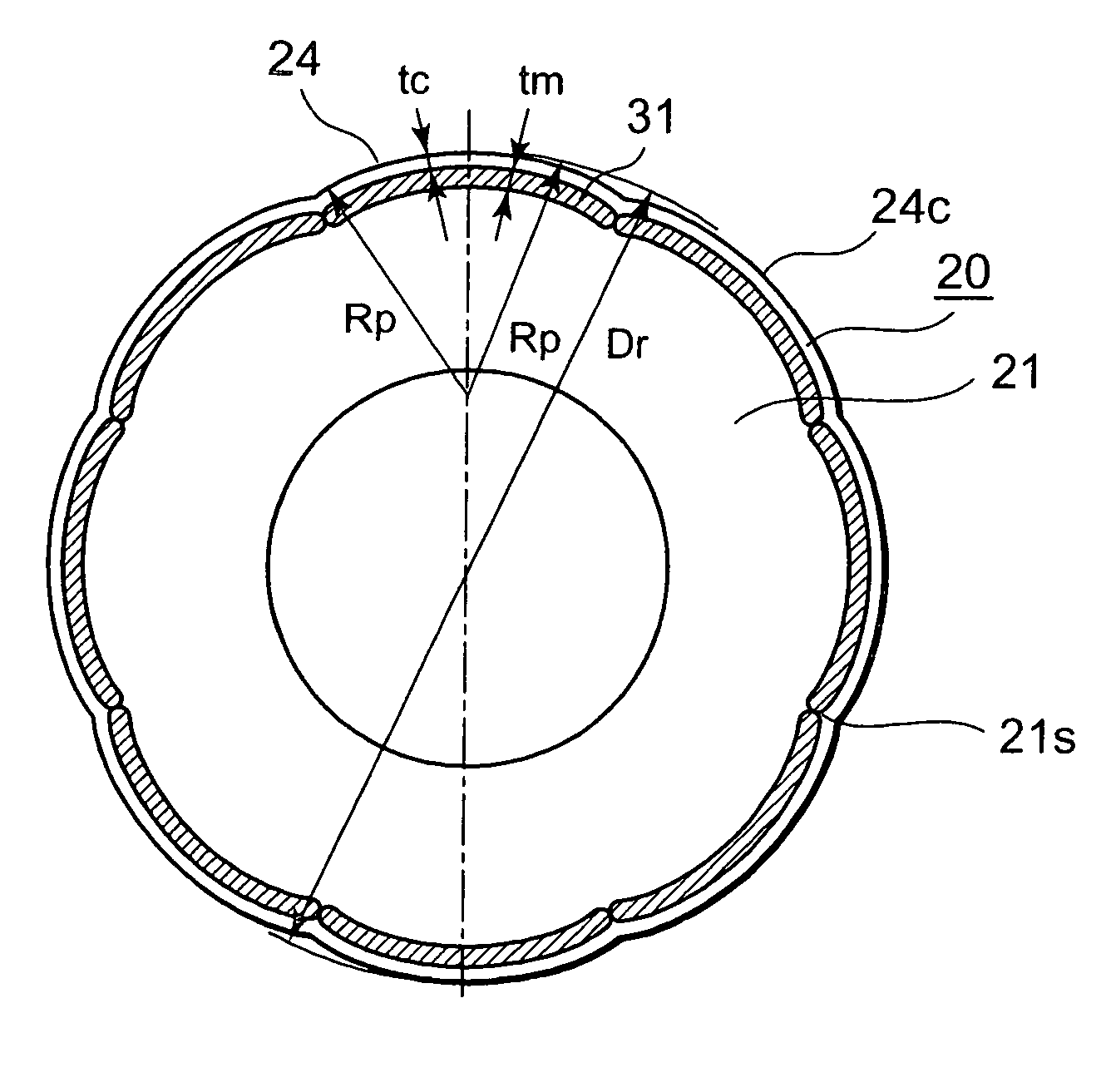
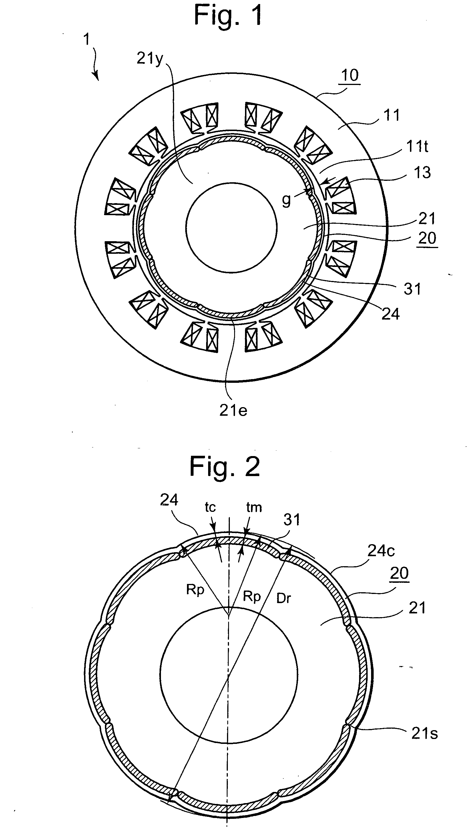
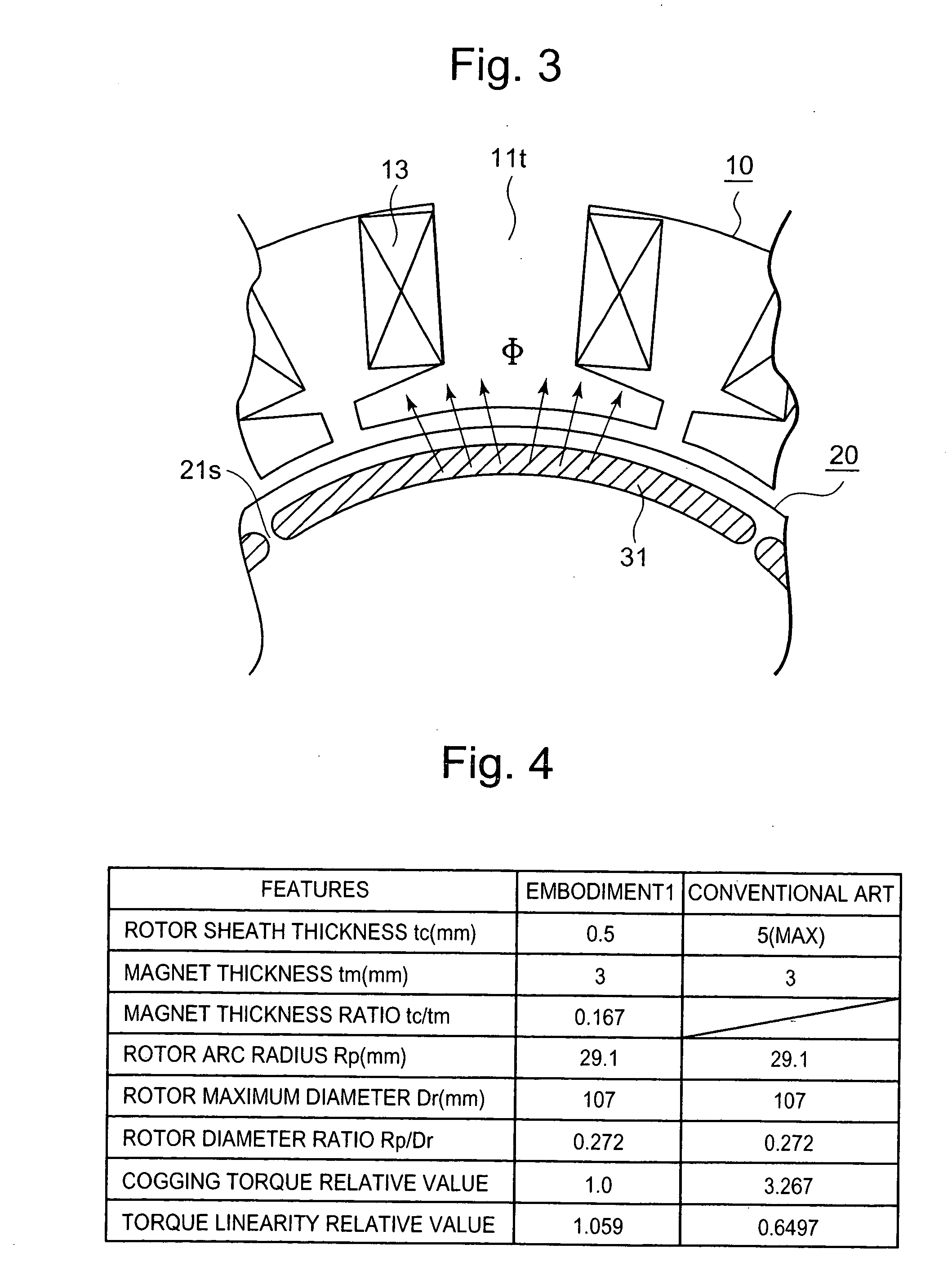
[0029] An embodiment of the present invention will be described using FIG. 1 through FIG. 3. FIG. 1 is a cross-sectional diagram of a permanent magnet motor according to the embodiment of the present invention, FIG. 2 is a cross-sectional diagram of a rotor in the permanent magnet motor illustrated in FIG. 1, and FIG. 3 is an enlarged partial cross-sectional diagram illustrating magnetic flux flow from the rotor to a stator in the permanent magnet motor illustrated in FIG. 1.

[0030] In FIG. 1 and FIG. 2, the permanent magnet motor 1 includes: a stator 10 composed of a stator iron core 11 made by die-cutting thin electromagnetic steel sheets, and by laminating the electromagnetic steel sheets, and having stator coils 13 wound around twelve salient poles 1 it; and an eight-pole rotor 20 having permanent magnets 31. The permanent magnet motor is configured so that the number of poles of the rotor 20 is 2n, and the number of salient poles lit of the stator 10 is 3n, where n is a positiv...

embodiment 2

[0057] Another embodiment of the present invention will be described according to FIG. 8. FIG. 8 is an enlarged partial cross-sectional diagram of the outermost portion of the rotor according to the embodiment of the invention.

[0058] There is a maximum rotating velocity as an important characteristic of the permanent magnet motor, other than the cogging torque and the torque linearity. The reason is that, if the maximum rotating velocity is raised, a machine driven by the motor can be operated in high speed, so that productivity can be enhanced.

[0059] However, as illustrated in FIG. 8, in the permanent magnet motor in which magnet slots 22 are provided in the rotor 20, and the permanent magnets 31 are inserted into the magnet slots 22 and fixed by adhesive agents or the like, if the maximum rotating velocity is raised, the stress concentrates in the corner portions at both ends of the magnet slots 22, whereby fixing the permanent magnets 31 can be adversely affected.

[0060] Theref...


PUM


Abstract

A permanent magnet motor 1 includes a rotor in which permanent magnets 31 are fixed. In the rotor 20, the outer peripheral shape of rotor magnetic-pole portions 24 is formed so that, in the circumferentially central portion, the distance from the center of the rotor iron core 21 is longest, and, at the inter-polar space, the distance from the center of the rotor iron core is shortest, and so that the outermost surface of the rotor magnetic-pole portions 24 forms an arc, and given that sheath thickness tc formed by the outer-side surface of each permanent magnet 31 and the outermost surface of each rotor magnetic-pole portion 24 is practically constant, and letting the thickness of the permanent magnets be the magnet thickness tm, then the relation tc/tm≦0.25 is satisfied.

Description

TECHNICAL FIELD [0001] The present invention relates to remedying cogging torque and improving torque linearity characteristics in permanent magnet motors having permanent magnets. BACKGROUND ART [0002] A conventional permanent magnet motor will be described referring to Japanese Laid-Open Patent Publication 119175 / 1987. The permanent magnet motor (henceforth referred to as “surface magnet motor”) such as this has a rotor provided with a plurality of permanent magnets fixed to the periphery of a rotary shaft, spacers between the permanent magnets, and pressing members formed of non-magnetic material for pressing radially on the surface of the permanent magnets. [0003] In terms of this surface magnet motor, since the magnets are fixed to the surface of the rotor, the surface magnet motor has excellent torque linearity characteristics in terms of linearity between torque and current. Thus, under high load, large torque can be obtained with small current, providing excellent controllab...

Claims


Application Information

Patent Timeline
Patent Type & Authority Applications(United States)
IPC IPC(8): H02K1/27
CPCH02K1/276
Inventor KIKUCHI, TOMOHIROMIYAZAKI, TAKASHIKOMETANI, HARUYUKIYAMAGUCHI, SHINICHI
Owner MITSUBISHI ELECTRIC CORP
Why Eureka
Try Eureka