Piezo-driven micro-droplet jet generator

a technology of jet generator and micro-droplet, which is applied in printing and other directions, can solve the problems of reducing the piezoelectric effect of the piezoelectric element to the point of damaging the piezoelectric element, conventional piezoelectric jet generators are not usable in conjunction with etching liquid, and not allowing for the ejection of micro-sized droplets

Inactive Publication Date: 2006-06-22
IND TECH RES INST
View PDF3 Cites 10 Cited by
  • Summary
  • Abstract
  • Description
  • Claims
  • Application Information

AI Technical Summary

Benefits of technology

[0009] It is the object of the present invention to provide a piezo-driven micro-droplet jet generator which is not damaged by etching liquid and which operates with higher pressure to allow for ejection of micro-sized droplets.
[0010] The main characteristic of the present invention lies in having a piezoelectric plate that is separated by a membrane from liquid, so that etching liquid will not damage the piezoelectric plate. Furthermore, in a rest state, the membrane touches an ejection plate. During a vibrating movement, a gap between the membrane and the ejection plate with varying width results. Due to the small width of the gap, the vibrating movement causes high pressure of liquid in the gap, driving out liquid through ejection holes in the ejection plate. Increased pressure allows for smaller ejection holes and an ejection of smaller droplets.

Problems solved by technology

However, if piezoelectric material is exposed to etching liquid for an extended time period, piezoelectric effect thereof is diminished to the point of damaging the piezoelectric element.
Therefore, conventional piezoelectric jet generators are not usable in conjunction with etching liquid.
For ejecting droplets, the nozzles need to have minimum sizes, not allowing for ejection of micro-sized droplets.

Method used


Image

  • Piezo-driven micro-droplet jet generator
  • Piezo-driven micro-droplet jet generator
  • Piezo-driven micro-droplet jet generator

Examples


Embodiment Construction

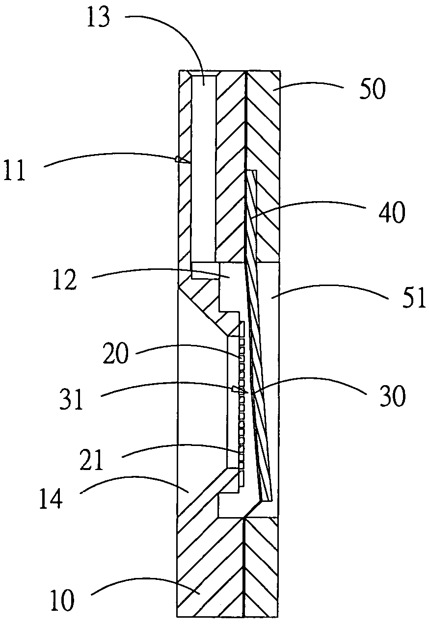
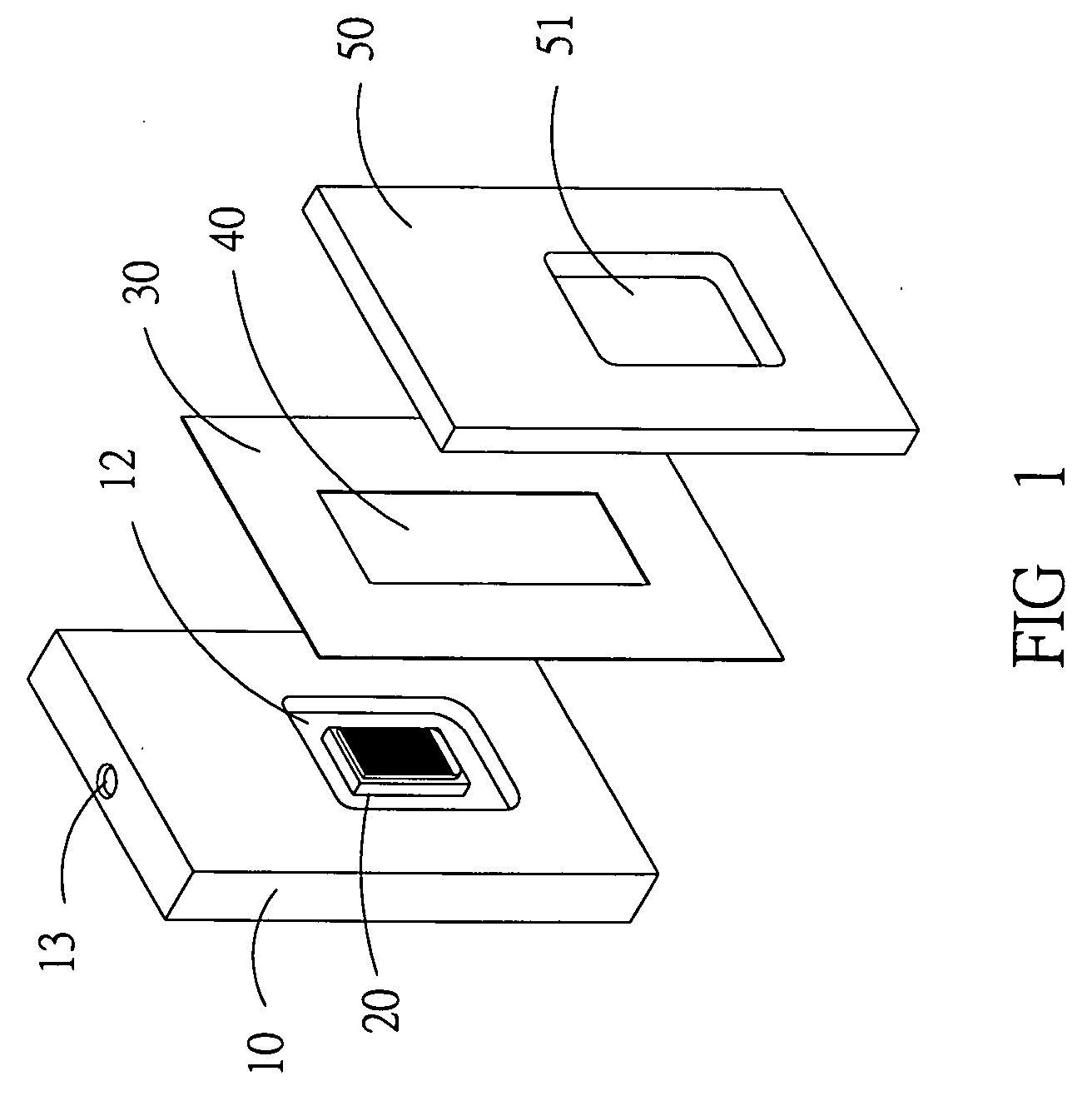
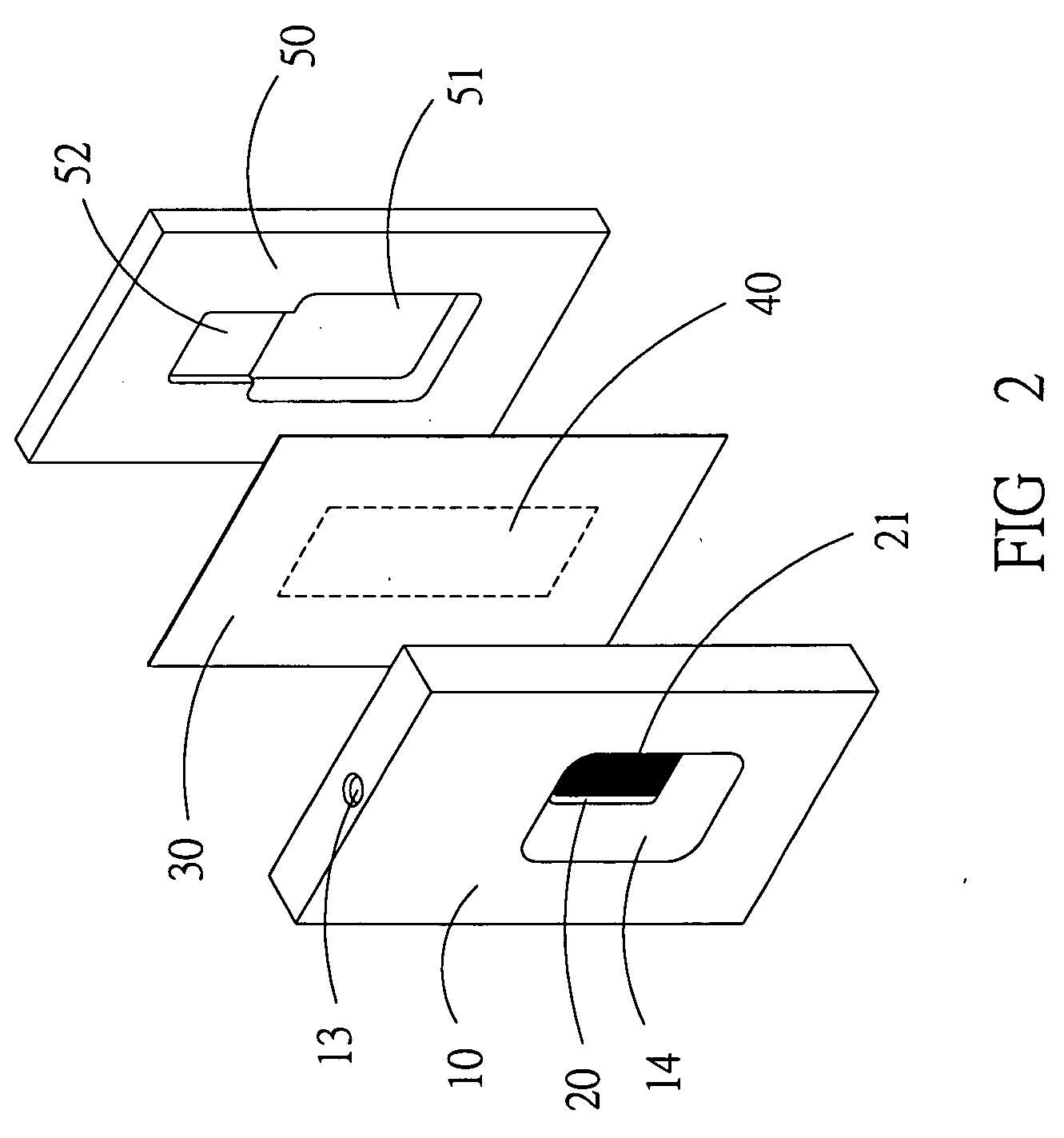
[0016] As shown in FIGS. 1 and 2, the piezo-driven micro-droplet jet generator of the present invention comprises: an ejection seat 10; an ejection plate 20; a membrane 30; a piezoelectric plate 40; and a base plate 50.

[0017] The ejection seat 10 has a mounting hole 14 in a central position, accommodating the ejection plate 20. The ejection plate 20 is a flat plate having a plurality of ejection holes 21, through which a liquid is ejected. A flow path 11 runs inside the ejection seat 10, having a pathway 12 running around the ejection plate 20 and an inlet connecting the pathway 12 with an outer side of the ejection seat 10. Liquid entering the inlet 13 from the outside is thus allowed to flow to the pathway 12 and further to a gap between the ejection plate 20 and the membrane 30.

[0018] As shown in FIGS. 2-3, the membrane 30 is placed between the ejection seat 10 and the base plate 50, having a front side facing the ejection plate 20 and a rear side. The piezoelectric plate 40 is...


PUM


Abstract

A piezo-driven micro-droplet jet generator comprises an ejection seat, having an ejection plate with a plurality of ejection holes; a membrane, having a front side facing the ejection seat and a rear side; a piezoelectric plate, placed at the rear side of the membrane, at least partly touching the membrane and, when electric voltage is applied, driving a vibrating movement of the membrane towards the ejection plate; a base plate, at four corners thereof fastened to the ejection seat and to the membrane; and a flow path inside the ejection seat, allowing liquid to be let into a space inside the ejection seat; wherein liquid between the membrane and the ejection plate upon the vibrating movement undergoes pressure, being ejected through the plurality of ejection holes.

Description

BACKGROUND OF THE INVENTION [0001] 1. Field of the Invention [0002] The present invention relates to a piezo-driven micro-droplet jet generator, particularly to a micro-droplet jet generator having a piezo-driven membrane and a plurality of micro-sized holes through which droplets are ejected. [0003] 2. Description of Related Art [0004] Microelectronic technology has made great progress in recent years and is subject of intensive research and development efforts. Micro-droplet jet generators have found wide use in ink-jet printers. Since ejection speed and flow are precisely controllable, further applications of micro-droplet jet generation technology are biotechnology, micro-coating, controlling of tiny jet quantities and scent generators. [0005] Conventional micro-droplet jet generators are mainly of two types, thermal bubble and piezoelectric jet generators. Since the present invention relates to piezoelectric technology, thermal bubble jet generators will not be mentioned furthe...

Claims


Application Information

Patent Timeline
Patent Type & Authority Applications(United States)
IPC IPC(8): B41J2/045
CPCB41J2/14282
Inventor GAU, TIEN-HOPENG, YU-YINCHIEN, CHIN-PIN
Owner IND TECH RES INST
Why Eureka
Try Eureka