Inkjet Head and Process of Manufacturing the Inkjet Head

a technology of inkjet head and manufacturing process, which is applied in the direction of printing, inking apparatus, etc., to achieve the effect of preventing deformation of metal plates

Active Publication Date: 2006-06-22
BROTHER KOGYO KK
View PDF5 Cites 28 Cited by
  • Summary
  • Abstract
  • Description
  • Claims
  • Application Information

AI Technical Summary

Benefits of technology

[0011] However, in the inkjet head constructed according to the present invention, the laminated structure body is formed with the atmosphere communication channel diverging from the network of ink channels and extending toward the exterior of the laminated structure body, so as to open outside of the laminated structure body in a process of manufacturing the inkjet head, thereby enabling the gas to be reliably evacuated from the network of ink channels toward the exterior of the laminated structure body through the atmosphere communication channel. The reliable evacuation of the gas in the process of manufacturing the inkjet head makes it possible to prevent the local deformation of the laminated structure body due to expansion and contraction of the gas in the diffusion welding, and also to prevent failure of fixation of the metal plates. Further, the atmosphere communication channel is sealed at its opening after the plurality of metal plates have been fixed to each other by the diffusion welding, so that the ink does not leak outside the laminated structure body through the atmosphere communication channel after the network of ink channels has been filled with the ink.
[0013] Since each of the at least one common ink chamber is provided to supply the ink to the plurality of nozzles, the volume of the common ink chamber is made relatively large. This means that the expansion and contraction of the gas within the common ink chamber could easily cause deformation of a portion of the laminated structure body defining the common ink chamber. However, in the inkjet head according to the second aspect of the invention, since the atmosphere communication channel diverges directly from one of the at least one common ink chamber, namely, is connected to one of the at least one common ink chamber, the gas can be reliably evacuated from the one of the at least one common ink chamber toward the exterior of the laminated structure body through the atmosphere communication channel, making it possible to reliably prevent deformation of the metal plates providing the laminated structure body.
[0016] However, in the inkjet head constructed according to the third aspect of the invention, the laminated structure body is formed with the second atmosphere communication channel diverging from the network of gas channels and extending toward the exterior of the laminated structure body, so as to open outside of the laminated structure body in a process of manufacturing the inkjet head. This construction enables the gas to be reliably evacuated from the network of gas channels toward the exterior of the laminated structure body through the second atmosphere communication channel. Further, the second atmosphere communication channel is sealed at its opening after the plurality of metal plates have been fixed to each other by the diffusion welding, so as to prevent the ink from entering the network of gas channels via the second atmosphere communication channel, for thereby making it possible to maintain the function of the at least one damping chamber for damping the pressure fluctuation.
[0020] In the manufacturing process according to the present invention, the atmosphere communication channel is formed in at least one of the metal plates in the first step, such that the atmosphere communication channel diverges from the network of ink channels, and extends toward an exterior of the laminated structure body so as to open outside the laminated structure body. In the second step following the first step, the metal plates are fixed to each other, by heating the metal plates, while the metal plates superposed on each other are being gripped or pressed between by the pair of members. Since the second step is implemented with presence of the atmosphere communication channel the gas can be reliably evacuated from the network of ink channels through the atmosphere communication channel during the second step, making it possible to prevent deformation of the metal plates arising from expansion and contraction of the gas. Further, since the atmosphere communication channel is sealed at its opening in the third step following the second step, the ink does not leak outside the laminated structure body through the atmosphere communication channel after the network of ink channels has been filled with the ink.

Problems solved by technology

Therefore, the fluctuation of the pressure in each of the at least one common ink chamber is likely to cause deformation of particularly, a portion of the laminated structure body that defines each of the at least one common ink chamber.

Method used


Image

  • Inkjet Head and Process of Manufacturing the Inkjet Head
  • Inkjet Head and Process of Manufacturing the Inkjet Head
  • Inkjet Head and Process of Manufacturing the Inkjet Head

Examples


Embodiment Construction

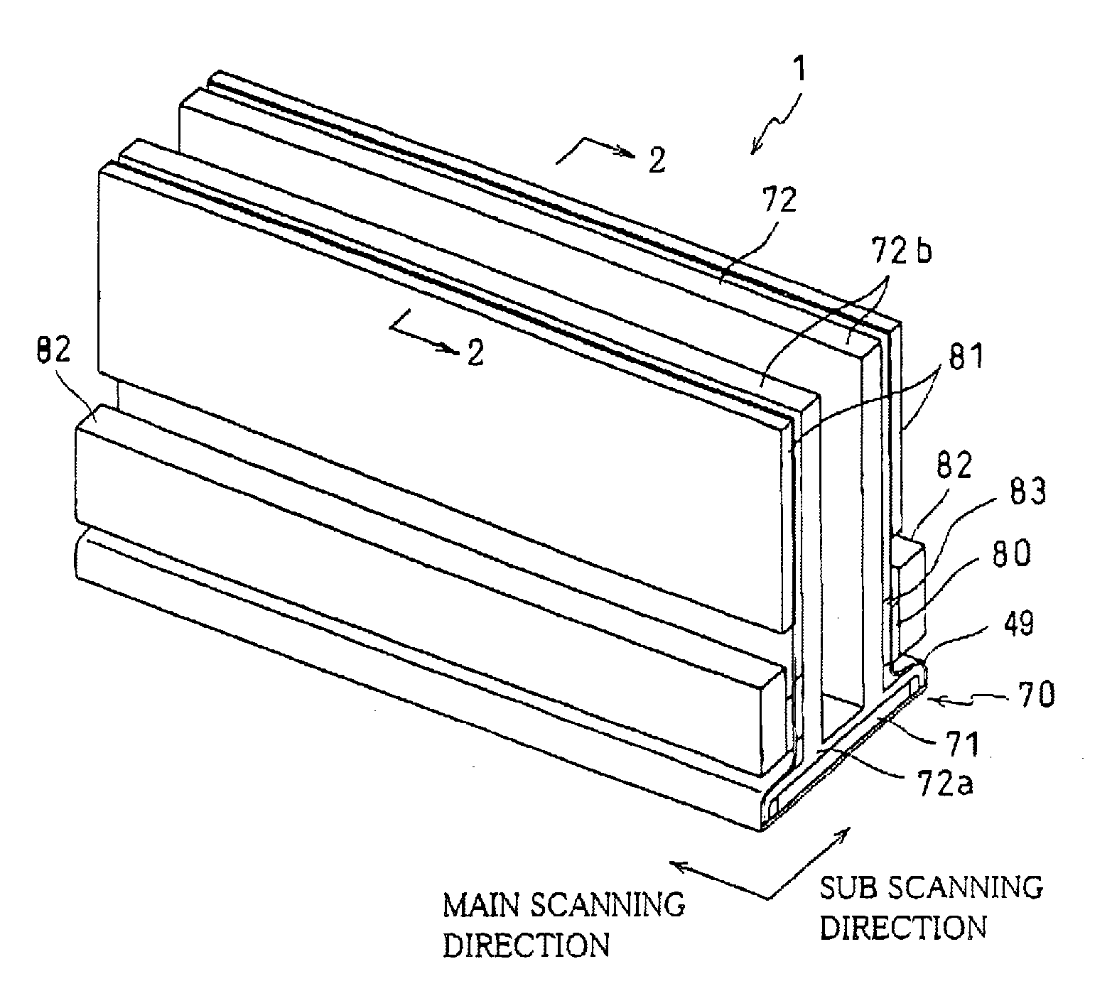
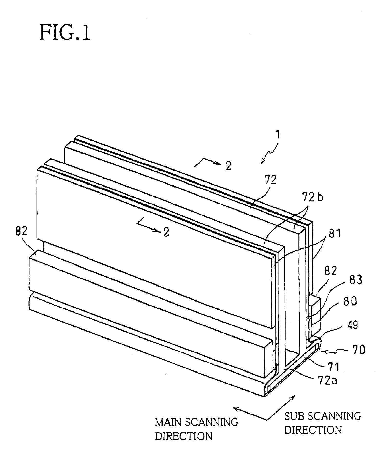
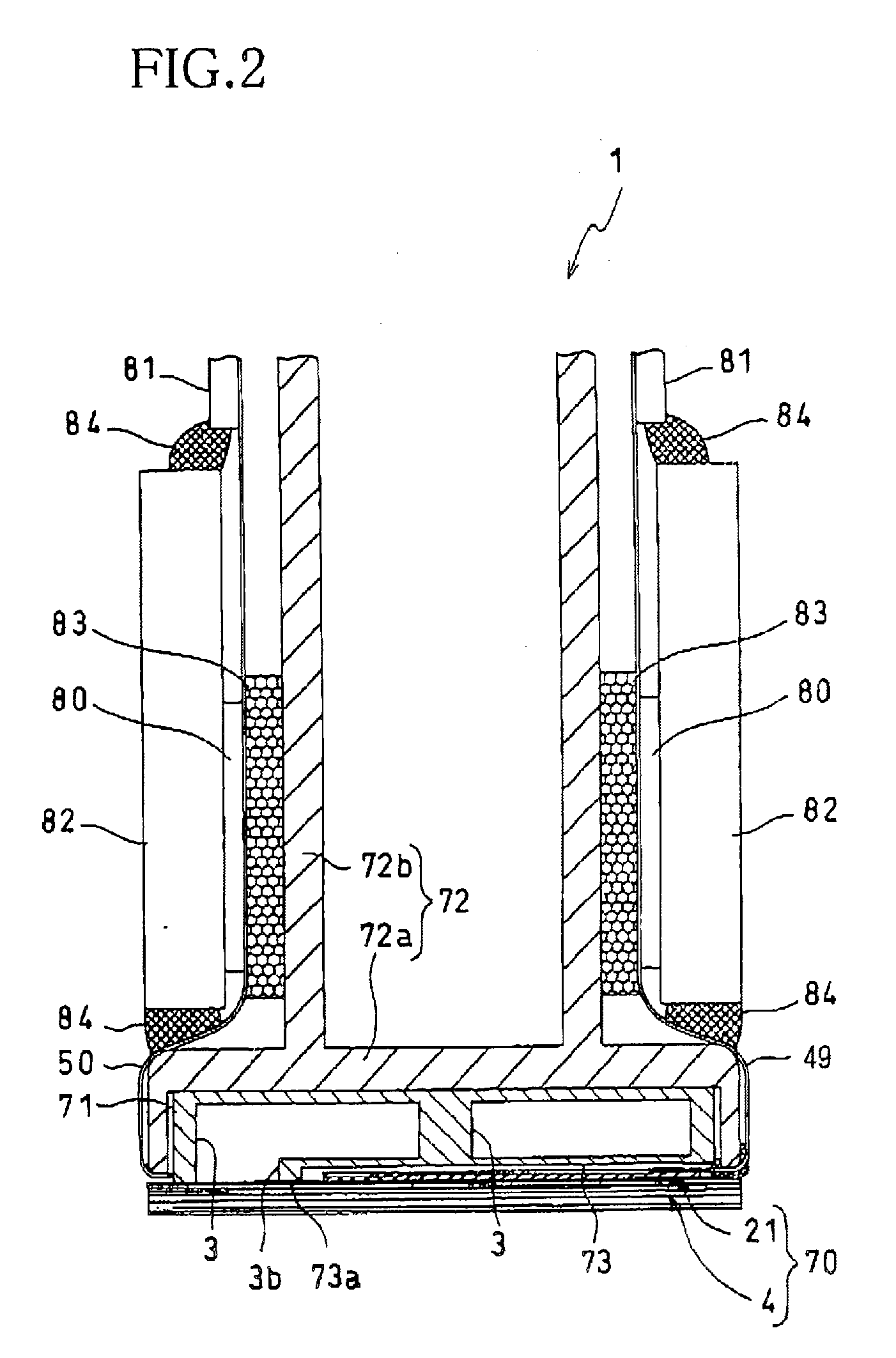
[0041] There will be described an embodiment of the present invention with reference to the accompanying drawings. FIG. 1 is a perspective view of an inkjet head 1 constructed according to the embodiment of the invention, while FIG. 2 is a cross sectional view taken along line 2-2 of FIG. 1. This inkjet head 1 is to be installed on an inkjet printer (not shown), so as to be operable to perform a recording operation, by ejecting an ink toward a recording medium (e.g., paper sheet) that is fed by a feeding device of the inkjet printer. As shown in FIGS. 1 and 2, the inkjet head 1 includes: a main body 70 which has a rectangular flat surface elongated in a main scanning direction of the printer and which is operable to eject the ink toward the recording medium; a base block 71 which is disposed above the main body 70 and which defines therein two ink storage chambers 3; and a holder 72 which holds the main body 70 and the base block 71. It is noted that each of the two ink storage cham...


PUM


Abstract

An inkjet head including an ink channel unit defining a network of ink channels which provides at least one common ink chamber and a plurality of nozzles held in communication with the at least one common ink chamber. The ink channel unit includes a laminated structure body that is provided by a plurality of metal plates superposed on each other. The laminated structure body has at least the at least one common ink chamber and an atmosphere communication channel which diverges from the network of ink channels. The atmosphere communication channel extends toward an exterior of the laminated structure body, so as to open outside the laminated structure body. The atmosphere communication channel is sealed at its opening. Also disclosed is a process of manufacturing the inkjet head.

Description

[0001] This application is based on Japanese Patent Application No. 2004-370339 filed in Dec. 22, 2004, the content of which is incorporated hereinto by reference. BACKGROUND OF THE INVENTION [0002] 1. Field of the Invention [0003] The present invention relates to an inkjet head operable to eject an ink onto a recording medium, and a process of manufacturing the inkjet head. [0004] 2. Discussion of Related Art [0005] Conventionally, there is known, as an inkjet head operable to eject an ink, an inkjet head including an ink channel unit which defines a network of ink channels and which includes a laminated structure body provided by a plurality of plates superposed on each other. US 2004 / 0183867 A1 (corresponding to JP-2004-276562A) discloses such an inkjet head including an ink channel unit defining a manifold chamber, a plurality of individual ink channels and a plurality of nozzles which are held in communication with the manifold chamber via the respective individual ink channels...

Claims


Application Information

Patent Timeline
Patent Type & Authority Applications(United States)
IPC IPC(8): B41J2/045
CPCB41J2/14209B41J2/1609B41J2/1623B41J2/1626B41J2002/14217B41J2002/14225B41J2002/14306B41J2002/14419B41J2002/14459B41J2202/20
Inventor CHIKAMOTO, TADANOBU
Owner BROTHER KOGYO KK
Why Eureka
Try Eureka