This helps you quickly interpret patents by identifying the three key elements:
Problems solved by technology
Method used
Benefits of technology
Benefits of technology
[0012] The invention provides an apparatus and method for rapidly inspecting a substrate by illuminating an area of a substrate that is larger than a diffraction-limited spot without undesirable interference effects.
[0013] The invention provides an apparatus and method for illuminating a large area of a substrate using high-NA imaging optics and using imaging detectors without incurring undesirable coherence interference effects.
Problems solved by technology
Lasers, which are commonly used in inspection systems produce undesirable coherent phenomena in imaging systems, such as ringing of edges and speckles.
Schemes exist for destroying the coherence of laser sources, but they inevitably add to the system's complexity and reduce optical power.
Throughput is limited by the spot size and the scan rate.
However, if these spots are not spatially separated, image distortions may occur due to coherent interference effects.
However, when using imagine detectors, the bright-field images may suffer undesirable distortion due to coherence effects in the form of ringing at feature edges, if there is mismatch between the NA of the collection optics and the imaging optics.
Method used
Image
Click on the blue label to locate the original text in one second.
Reading with bidirectional positioning of images and text.
Examples
first embodiment
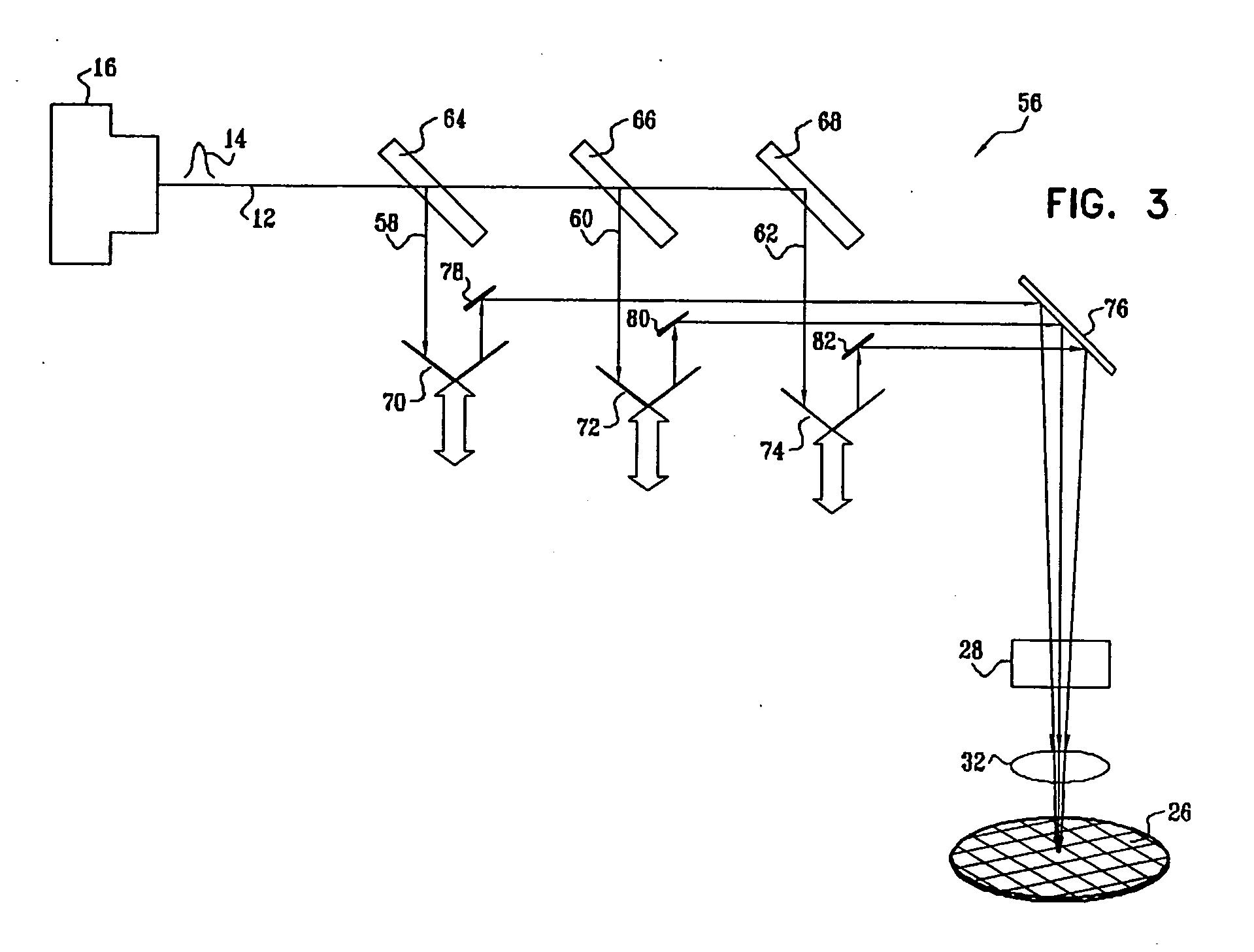
[0081] Reference is now made to FIG. 3, which is a schematic illustration of an optical inspection system 56, which is constructed and operative in accordance with a disclosed embodiment of the invention.
[0082] The beam 12 is split into a plurality of beamlets 58, 60, 62 by beamsplitters 64, 66, 68, respectively. The relative reflectance and transmittance of each of the beamsplitters 64, 66, 68 are typically (but not necessarily) chosen so that all the beamlets 58, 60, 62 have equal intensities. The beamlets 58, 60, 62 are received respectively by retroreflectors 70, 72, 74. The beamlets 58, 60, 62 are then directed to a reflector 76 by reflectors 78, 80, 82, after which they pass through the scanner 28, beam processing optics 34 and focusing optics 32, and impinge on the substrate 26. The retroreflectors 70, 72, 74 form free-space delay lines. They are disposed so that the optical paths of the beamlets 58, 60, 62 are of different lengths. Thus, the beamsplitters 64, 66, 68 and the...
second embodiment
[0085] Reference is now made to FIG. 4, which is a schematic illustration of an optical inspection system 84, which is constructed and operative in accordance with an alternate embodiment of the invention. The description of FIG. 4 should be read in conjunction with FIG. 3. The arrangement of the system 84 is similar to the system 56, except now, the beamsplitters 64, 66, 68 (FIG. 3) are replaced by a series of reflective edge filters 86, 88, 90, which produce beamlets 92; 94, 96, each having a unique waveband.
[0086] The ultrafast pulse 14 inherently contains a large spectral bandwidth, with a minimum bandwidth Δν given by: Δν·τ≅1. The beamlets 92, 94, 96 are spatially separated, and not only are dispersed temporally as disclosed in the discussion of the embodiment of FIG. 3, but are also distributed according to wavelength, using the edge filters 86, 88, 90, which disperse the beamlets 92, 94, 96 according to wavelength. For example, a typical 100 fsec pulse with a central wavelen...
third embodiment
[0089] Reference is now made to FIG. 5, which is a schematic illustration of an optical inspection system 100, which is constructed and operative in accordance with an alternate embodiment of the invention. The system 100 is similar to the system 84 (FIG. 4). However, different time delays for the beamlets 92, 94, 96 are now achieved by transmitting the beamlets 92, 94, 96 respectively through optical fibers 102, 104, 106, each fiber having a different length. Thus, the optical paths followed by the beamlets 92, 94, 96 have unique lengths.
PUM
Abstract
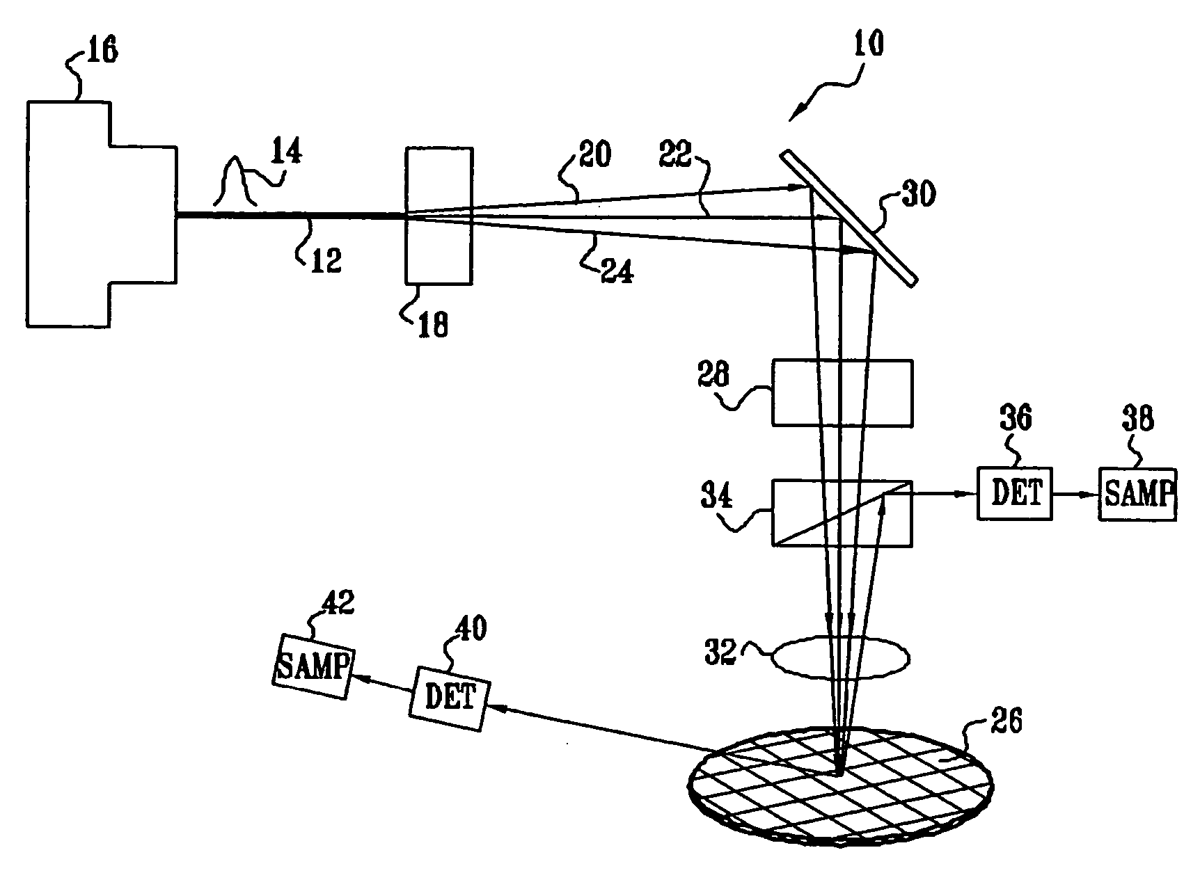
An optical inspection system rapidly evaluates a substrate by illumination of an area of a substrate larger than a diffraction-limited spot using a coherent laser beam by breaking temporal or spatial coherence. Picosecond or femtosecond pulses from a modelocked laser source are split into a plurality of spatially separated beamlets that are temporally and / or frequency dispersed, and then focused onto a plurality of spots on the substrate. Adjacent spots, which can overlap by up to about 60-70 percent, are illuminated at different times, or at different frequencies, and do not produce mutually interfering coherence effects. Bright-field and dark-field detection schemes are used in various combinations in different embodiments of the system.
Description
CROSS-REFERENCE TO RELATED APPLICATIONS [0001] This application claims the benefit of U.S. provisional patent application No. 60 / 378,400 filed 6th May 2002 titled “High speed laser inspection system” and claims the benefit of United States provisional patent application No. 60 / 378,721 filed 7th May 2002 titled “Optical technique for detecting buried defects in opaque films”.BACKGROUND OF THE INVENTION [0002] 1. Field of the Invention [0003] This invention relates generally to systems and methods for detecting irregularities on a substrate. More particularly, this invention relates to systems and methods for detecting irregularities on the surface of silicon wafers or photomasks. [0004] 2. Description of the Related Art [0005] Semiconductor wafers are inspected prior to, during, and after patterning procedures. Optical inspection systems typically employ illumination optics and collection-detection optics for directing incident light from a light source onto a wafer to be inspected, ...
Claims
Application Information
Patent Timeline
Application Date:The date an application was filed.
Publication Date:The date a patent or application was officially published.
First Publication Date:The earliest publication date of a patent with the same application number.
Issue Date:Publication date of the patent grant document.
PCT Entry Date:The Entry date of PCT National Phase.
Estimated Expiry Date:The statutory expiry date of a patent right according to the Patent Law, and it is the longest term of protection that the patent right can achieve without the termination of the patent right due to other reasons(Term extension factor has been taken into account ).
Invalid Date:Actual expiry date is based on effective date or publication date of legal transaction data of invalid patent.

