

Connector with improved dual beam contacts
a dual-beam contact, connector technology, applied in the direction of coupling contact members, coupling device connections, coupling/insulating coupling contact members, etc., can solve the problems of increasing the cost of terminals and the assembly, weakening the contact arms, etc., and achieve the effect of reducing the concentration of stress
- Summary
- Abstract
- Description
- Claims
- Application Information
AI Technical Summary
Benefits of technology
Problems solved by technology
Method used
Image

Examples
Embodiment Construction
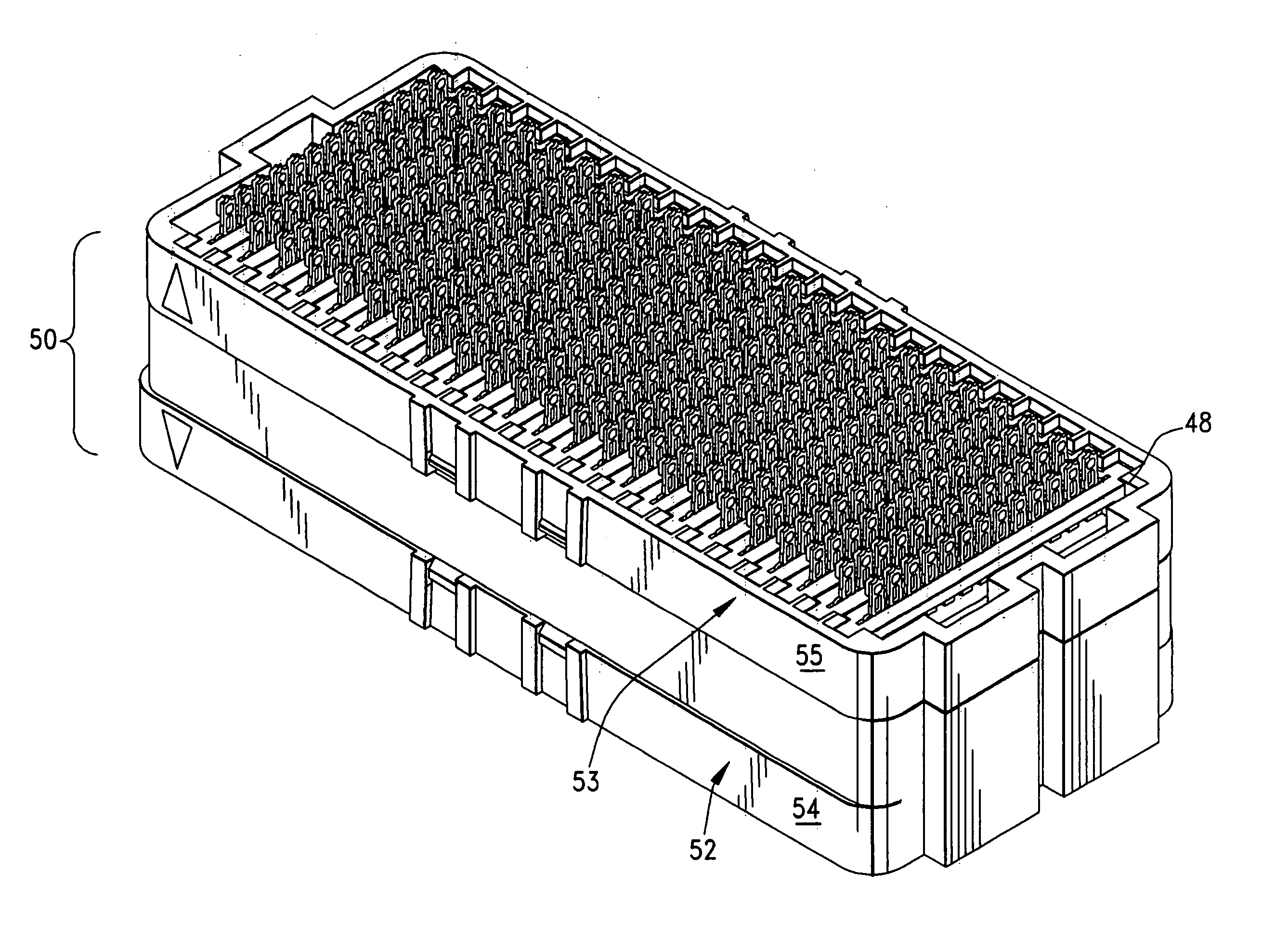
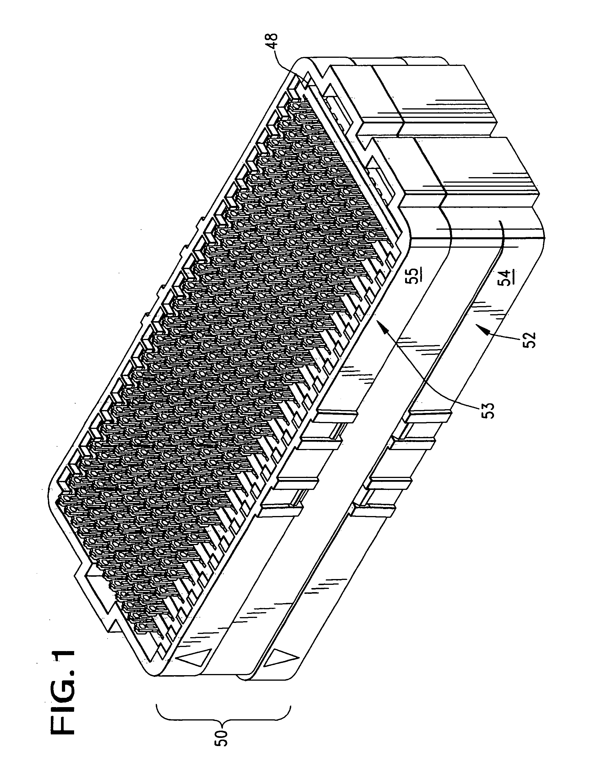
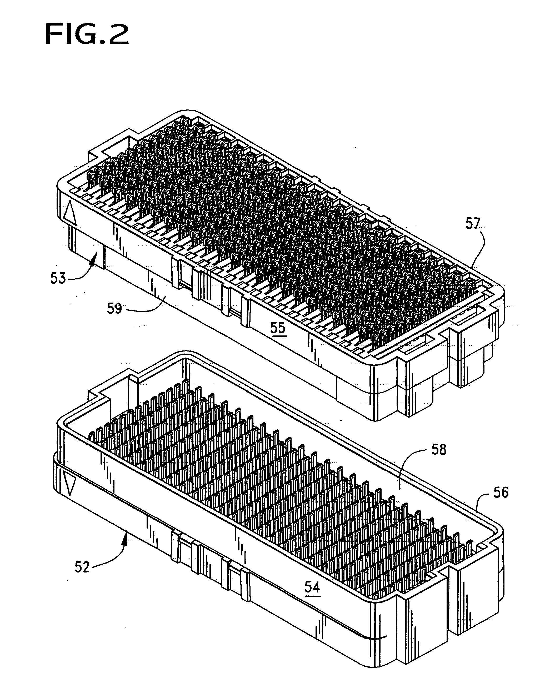
[0037]FIG. 1 illustrates a connector assembly 50 that is constructed in accordance with the principles of the present invention. The assembly 50 is comprised of two separate interengaging connector components 52, 53 (FIG. 2) that include a male connector component 52 and a female connector component 53. The terms “male” and “female” as used in this description refer to the structure of the terminals, and in this description, the male connector component 52 has a plurality of individual blade contacts that are received between arms of corresponding female terminals that are disposed in the female connector component 53.
[0038] Each connector component 52, 53 can be seen to include a plurality of conductive terminals that are supported in insulative housings 54, 55. Each such housing 54, 55 shown is seen to include an outer wall 56, 57 that defines a perimeter of the connector component and the male connector component 52 includes a hollow interior cavity 58 into which a mating portio...
PUM
 Abstract
Description
Claims
Application Information