Inner plenum dual wall liner

Active Publication Date: 2006-06-29
RAYTHEON TECH CORP
View PDF9 Cites 7 Cited by
  • Summary
  • Abstract
  • Description
  • Claims
  • Application Information

AI Technical Summary

Benefits of technology

[0007] This invention is a dual wall exhaust nozzle liner assembly that includes a plenum chamber for c

Problems solved by technology

Disadvantageously, the inability to impinge cooling flo

Method used


Image

  • Inner plenum dual wall liner
  • Inner plenum dual wall liner
  • Inner plenum dual wall liner

Examples


Example

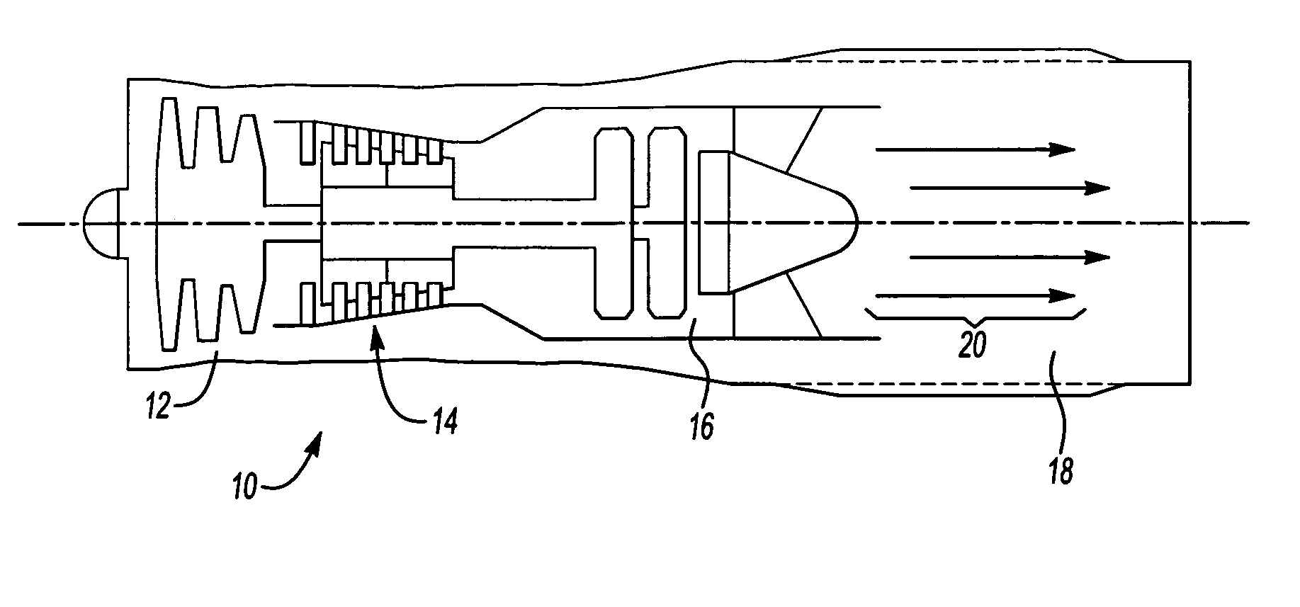
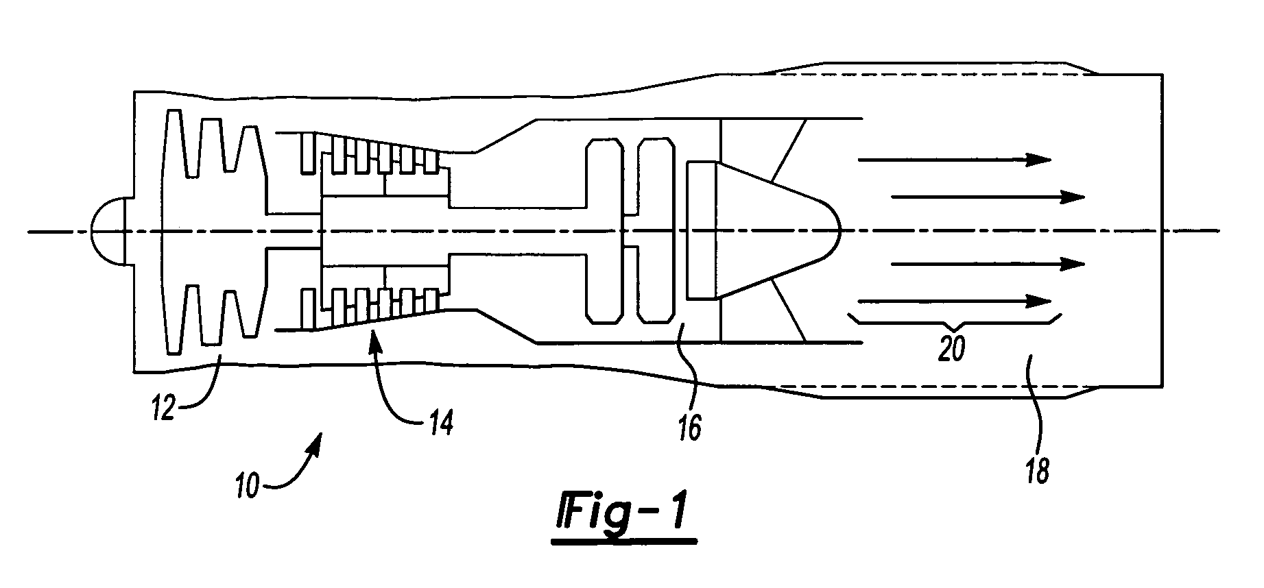
[0014] Referring to FIG. 1 a turbine engine assembly 10 includes a compressor 12, a combustor 14 and a turbine 16. The turbine engine assembly 10 operates in a known manner by feeding compressed air from the compressor 12 to the combustor 14. The compressed air is mixed with fuel and ignited to produce an axial flow of hot gases 20. A turbine 16 transforms the axial flow of hot gases 20 into mechanical energy to drive the compressor 12. The hot gases 20 are directed by an exhaust nozzle assembly 18 out of the engine assembly 10. The exhaust nozzle assembly 18 encounters extreme temperatures due to exposure to the hot gases 20 and is cooled by a flow of cooling air.

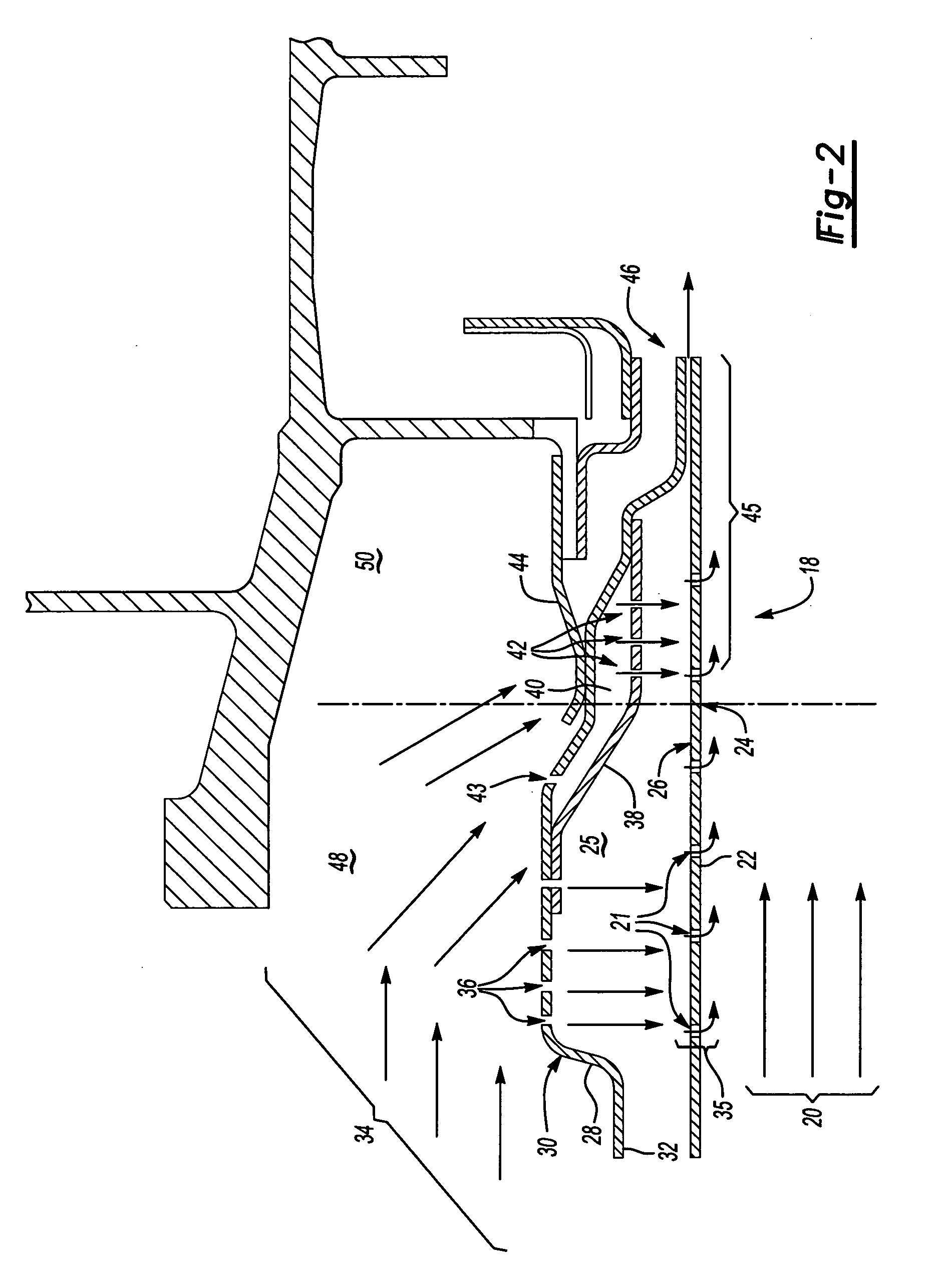
[0015] Referring to FIG. 2, an enlarged cross-section of an end portion of the example exhaust nozzle assembly 18 is shown. The example exhaust nozzle assembly 18 includes a dual wall construction having an inner liner 22 exposed to the hot gases 20 and an outer liner 28 spaced a radial distance from the inner liner 22 to...


PUM


Abstract

An exhaust nozzle assembly includes an inner liner exposed to hot combustion gases and an outer liner spaced a radial distance from the inner liner to form an annular chamber. The inner liner includes a hot side that is directly exposed to the hot combustion gas flow and a cold side is exposed to cooling air within the chamber. The outer liner includes an outer surface exposed to cooling air flow up to a restriction preventing communication of cooling air flow. A plenum is attached to the outer liner to define a plenum chamber that extends into an end portion. The plenum chamber receives cooling air flow from a supply opening and communicates that air to an end portion through a plurality of impingement openings that provide impingement flow of cooling air outboard of the restriction.

Description

[0001] The U.S. Government may have certain rights in this invention in accordance with Contract Number N00019-02-C-3003 awarded by the United States Navy.BACKGROUND OF THE INVENTION [0002] This invention relates generally to an exhaust liner for a turbine engine. More particularly, this invention relates to an exhaust liner with impingement cooling of an end portion of the exhaust liner. [0003] A gas turbine engine includes a compressor, a combustor and a turbine. Compressed air mixed with fuel in the combustor generates an axial flow of hot gases. The hot gases flow through the turbine and against a plurality of turbine blades. The turbine blades transform the flow of hot gases into mechanical energy for driving a rotor shaft that in turn drives the compressor. An exhaust liner assembly directs, contains, and protects other engine components from hot combustion gases exhausted from the turbine engine. [0004] The exhaust liner assembly typically includes a hot side liner and a cold...

Claims


Application Information

Patent Timeline
IPC IPC(8): F02K1/78
CPCF02K1/822Y02T50/675F05D2260/201Y02T50/60
Inventor FARAH, JORGE
Owner RAYTHEON TECH CORP
Why Eureka
Try Eureka