
Variable temperature cushion and heat pump

a cushion and variable temperature technology, applied in the field of variable temperature cushions and heat pumps, can solve the problems of air inside the pillow or pillow case that presents certain challenges

Inactive Publication Date: 2006-06-29
FEHER STEVE
View PDF29 Cites 79 Cited by
  • Summary
  • Abstract
  • Description
  • Claims
  • Application Information

AI Technical Summary

Benefits of technology

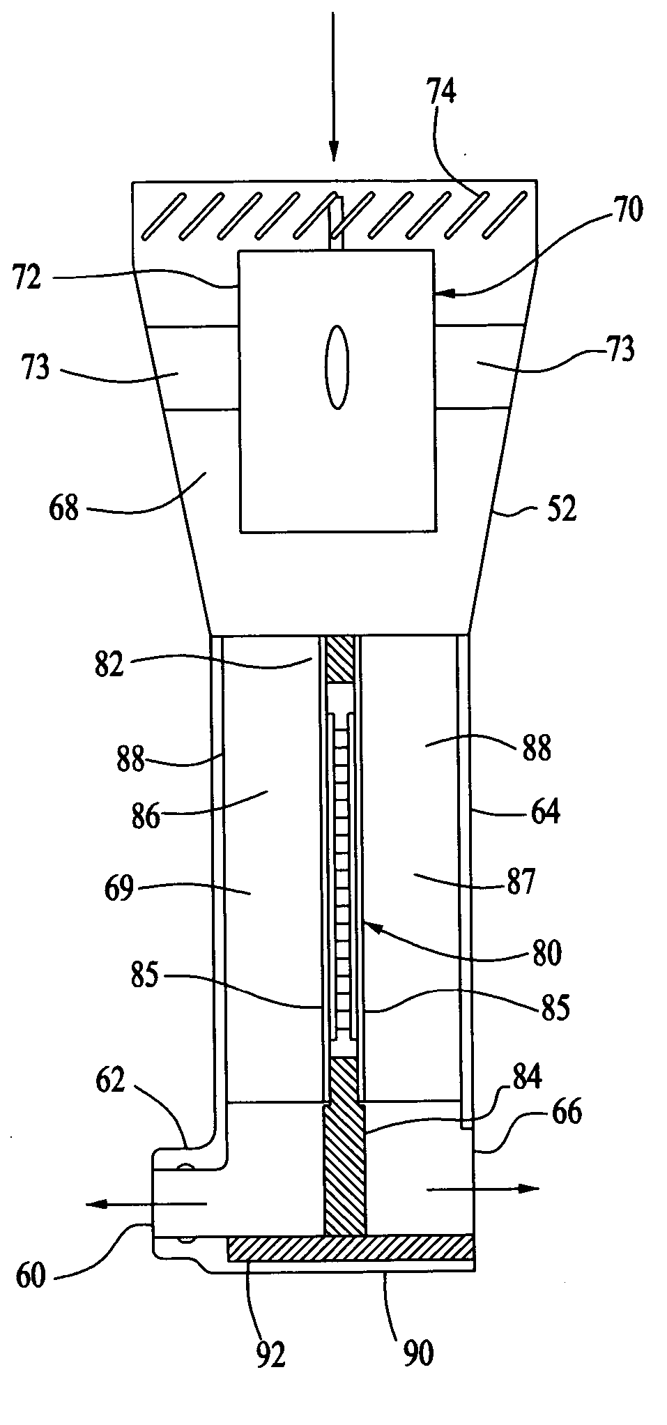
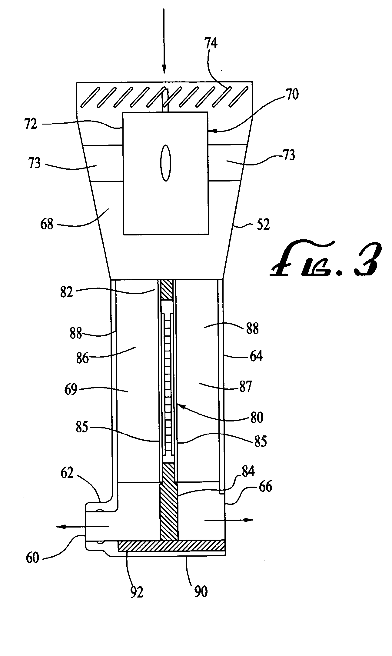
[0011] Another application of the heat pump technology of the present invention is in the field of air-conditioned bedding, or variable temperature mattresses, mattress pads, pillows and pillowcases or the like. A variable temperature pillowcase includes a top and a lower air impervious layer connected together forming a plenum, further containing a tubular spacer layer and having a plurality of outlet vents around the perimeter of the plenum. The pillowcase preferably has an opening on one end sized to receive a conventional pillow below the tubular spacer layer. A multi-channel air duct connects the plenum to the heat pump to minimize the noise generated by the air flow through the hoses. Still further, there is an optional noise cancellation system including a microphone, a processor and a speaker for detecting a noise waveform and determining and broadcasting a waveform 180 degrees out of phase with the noise waveform.

Problems solved by technology

Conditioning the air inside a pillow or pillow case presents certain challenges, however.

Method used


Image

  • Variable temperature cushion and heat pump
  • Variable temperature cushion and heat pump
  • Variable temperature cushion and heat pump

Examples


Embodiment Construction

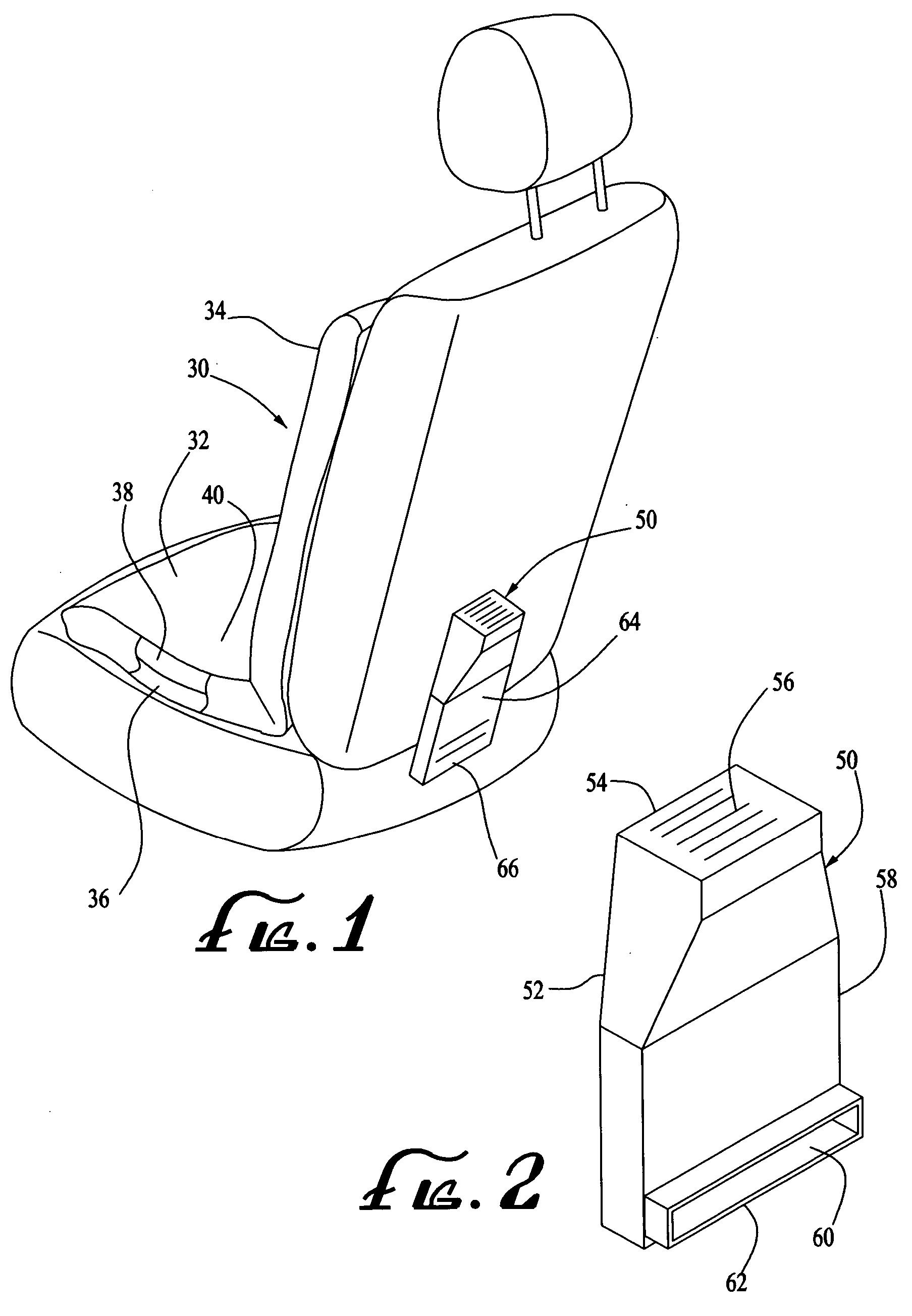
[0034] Initially referring to FIGS. 1-16, a variable seat cushion 30 and heat pump 50 may be described. The preferred embodiment is shown in terms of an aftermarket cushion 30 for placement atop a conventional vehicle seat, but alternatively the variable temperature hardware as described herein could be built into a new vehicle seat or sold as a kit of parts to convert a conventional vehicle seat into a variable temperature one selectively controlled by the user.

[0035] Now primarily referring to FIG. 1, the cushion 30 has a seat rest 32 and a backrest 34, and inside there is a tubular spacer layer 36 and an optional padding layer 38. Importantly, the tubular spacer layer 36 provides structure to facilitate flow of the air-conditioned air (described below) through the cushion 30 even when the user is seated on the seat rest 32 and leaning back against the backrest 34 which tends to compress the cushion 30 and cut off the airflow. The cushion cover 40 may be air permeable on the fron...


PUM


Abstract

A heat pump for use in a variable temperature cushion includes a housing with an inlet and a blower motor to draw in outside air to a two stage Peltier effect module that forms a sealed wall between a sub-cool side and a warm side of the housing. At the bottom of the housing are a pair of outlets and a condensate trap spanning across that facilitates condensate transfer from the cool side to the warm side for evaporation out of the warm side outlet. The heat pump also preferably includes a heat pipe from the warm side to the cool side to transfer heat and reheat the air (at a lower relative humidity) exiting through the cool outlet. Applications of the heat pump include a variable temperature cushion such as a seat and backrest, or bedding such as a pillow. An air conditioned pillowcase includes a pair of air impervious layers connected together forming a plenum with tubular spacer material inside and having a plurality of outlet vents around the perimeter. A multi-channel air duct connects the plenum to the heat pump, and further there is an optional noise cancellation system, both to minimize noise from operation of the heat pump.

Description

BACKGROUND OF THE INVENTION [0001] 1. Field of the Invention [0002] The present invention relates to cushions or other devices that can be selectively cooled (or heated) by the user and an improved thermoelectric heat pump for use in such applications. [0003] 2. Description of the Related Art [0004] Air-conditioned seats are a reality in many luxury-car brands being sold in the United States. The configuration and advantages of such seats were described in two of Steve Feher's recent patents, U.S. Pat. Nos. 6,263,530 and 6,085,369. These seats work satisfactorily such that they have become a popular option for Lexus, Lincoln and other automakers, but efforts are ongoing to improve the operating efficiency and compactness of the associated heat pumps to cool better, use less energy and occupy less space. [0005] Besides merely reducing the temperature of the air within the seats and that bleeds through the seat covers, it would also be desirable to reduce the relative humidity of that...

Claims


Application Information

Patent Timeline
IPC IPC(8): F25B21/02F25B15/00F25B27/00
CPCB60N2/5635B60N2/5657B60N2/5685B60N2/5692
Inventor FEHER, STEVE
Owner FEHER STEVE
Learn More