Heat exchanger header with deformations

a heat exchanger and header technology, applied in the direction of heat exchanger fastening, heat exchange apparatus, stationary conduit assembly, etc., can solve the problems of significant negative impact and loss of heat exchanger strength during cold (non-thermally-heated) work, and achieve increased heat exchanger durability, increased pressure resistance, and increased material strength

Active Publication Date: 2006-06-29
VALEO SISTEMAS ELECTRICOS DE CAPITAL VARIABLE
View PDF7 Cites 16 Cited by
  • Summary
  • Abstract
  • Description
  • Claims
  • Application Information

AI Technical Summary

Benefits of technology

[0008] A heat exchanger of the present invention is preferably a heat exchanger useful in automotive application, more preferably a radiator or charger air cooler, (CAC), more preferably a charge air cooler or the like. Preferred embodiments of the present invention useful in automotive vehicles, are heat exchangers with cores and headers made of aluminum or aluminum alloys in processes such as the CAB process, that has a header (collector) with side wall on its periphery for receiving a seal member as well as a plastic tank member, wherein deformations (for example in the large sides of the side wall) are presented in the inner or outer wall. Non limiting examples of deformations can include notches, grooves, or protuberances, elevations, ribs, or the like depending which can be present on the interior or exterior of the tank. The deformations in the periphery of the header wall are preferably made after the brazing process. This prevents the reduction of the stiffness gained on the hardening of the stamping in cold work, and associated increase in product life span.
[0010] Preferred embodiments of the present invention provide additional strength to the headers of the core, without using the solutions such as overall thickening of materials. The header has a header portion connected to or otherwise attached or fixed (hereinafter ‘fixed’) to the core portion. The present invention advantageously provides a method for increasing the strength of the materials without such thickening, while retaining the advantage of increased pressure resistance and increased durability of the heat exchanger, even under repetitive cycles of pressure.
[0011] The durability of the heat exchangers with this type of design, preferably with plastic tanks, depends to a large extent on the strength of the crimping. Stresses produced by the internal pressure on the heat exchanger are distributed along the periphery of the header. The header tabs that hold the tanks, and, subsequently, the seat of the header, suffer stress. This effect is more significant when size increases, i.e. size of the tanks, width and height are larger.
[0012] The present invention provides for a way of strengthening or reinforcing area of or around the header joint of heat exchanger assemblies. The present invention, by providing for deformations, such as grooves, notches, projections or deformations, on the header, and, in particular grooves or notches, in or on the side wall of the header, increase the stiffness of the side wall. This increase in stiffness consequently produces additional strength at the header to tank joint to a level that even in highly elevated stress and pressure conditions, the crimping joint, is able to resist (not burst or otherwise bulge) to an extent where it withstands the internal pressure, and the heat exchanger header to joint remains intact.
[0013] Preferred embodiments of the present invention, therefore, provide for increased pressure resistance at the header to tank joint, particularly at the header to tank crimp joints, of the heat exchanger without any subsequent increase in material thickness. In more preferred embodiments, the overall material thickness, particularly in the header side wall, can even be reduced proportionally without any significant effect on pressure resistance.
[0015] In preferred method embodiments of the present invention, the process to build the deformations into to the header material is done with a subsequent increase the strength of the header physical properties. In most preferred embodiments, this deformation addition step in the process must be performed after the brazing to obtain the maximum advantage. Preferred process operations produce deformations on the header side walls of the core. These deformations increase the strength of the core to resist pressure to a greater degree, especially under areas of high stress, than non-deformed header side walls. As described above, the processes in accordance with the present invention produce deformations, such as ribs projections, or the like, particularly deformations on the side walls of the header that increase stiffness of the material.

Problems solved by technology

The crimp most often consists of a deformation on the header tabs that produces an interference with the plastic tanks.
Aluminum braze processes used in the production of heat exchangers have many advantages, but also have the disadvantage that the strength gained during the cold (non thermally-heated) work of the header is lost due to the re-crystallization of micro structures during the brazing.
However, these thicker materials mean a significantly negative impact from both a cost and a crimping process point of view.

Method used


Image

  • Heat exchanger header with deformations
  • Heat exchanger header with deformations
  • Heat exchanger header with deformations

Examples


Embodiment Construction

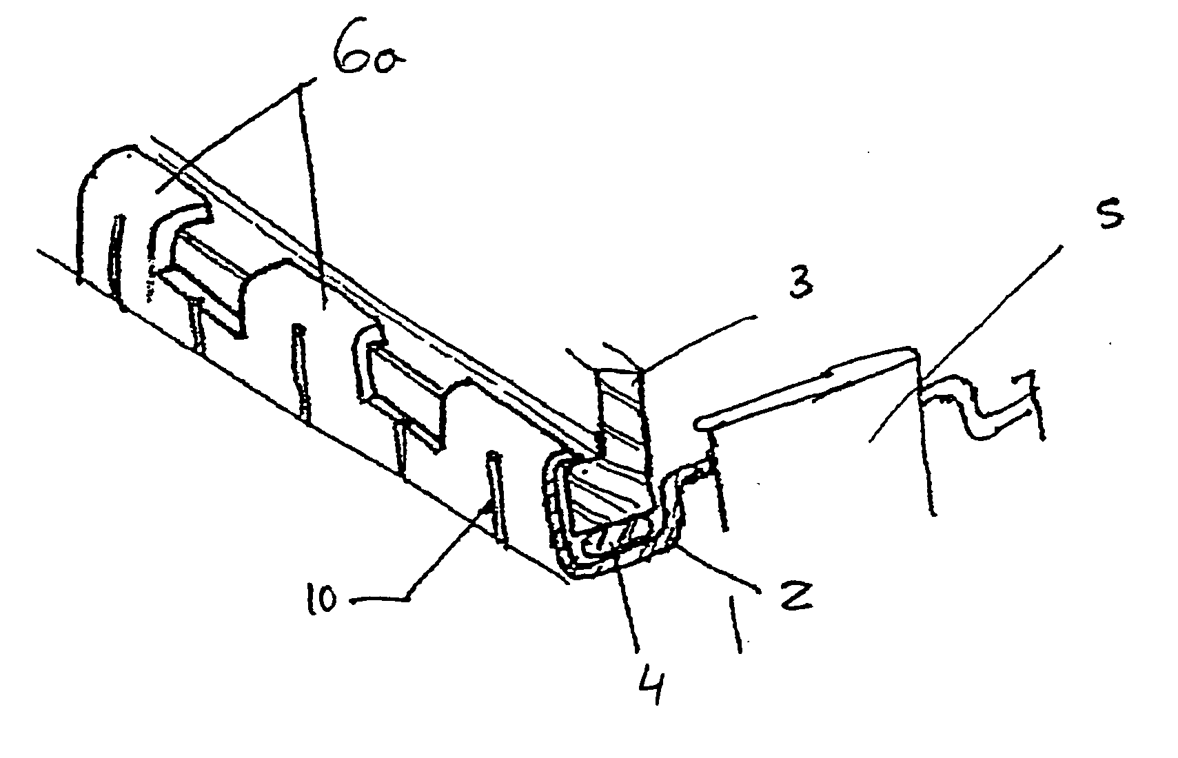
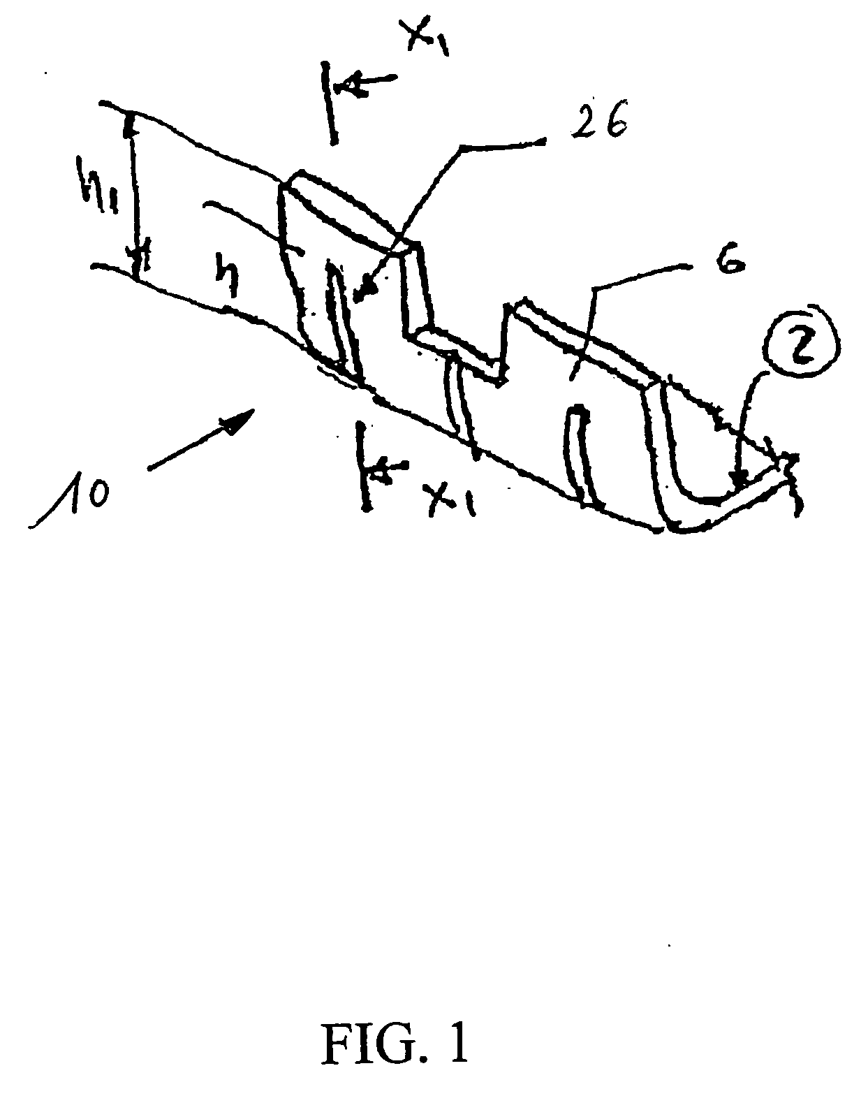
[0032] Referring to FIGS. 1-7, deformations (26) are added, preferably by a jig, to the side wall tab (hook) of the header (10). Interior surface of header (2) is shown.

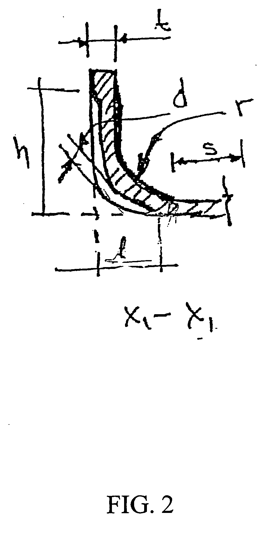
[0033] As shown in FIG. 2 for the deformations made on the outer side of the wall Depth of the deformation (d), height (h) length (l) and width (w) (see also (w3) of FIG. 10) are measured to confirm adequate function.

[0034] In a preferred embodiment of the present invention, the (h) dimension can be from about 10% to the full size of the tooth (h1). The width (w) can be from 0.1 mm to the end of the curve of the inside radio (r) with the intersection of the sealing surface (s). The depth (d) dimension can be from about 0.1 mm to max of 50% of the material thickness of the header core. Width (w3) can be from 0.2 mm to 3.0 mm, or otherwise, depending on the actual configuration of the heat exchanger.

[0035] Referring to FIGS. 3-7 are additional preferred embodiments of the present invention. The tab (6) is bent into ...


PUM

PropertyMeasurementUnit
widthaaaaaaaaaa
thicknessaaaaaaaaaa
areaaaaaaaaaaa

Abstract

The present invention has its object to provide a heat exchanger with plastic tanks type, wherein a seal member is regularly compressed and hooks or tabs of header core crimped in a uniform fashion. Deformations predominantly located in the large sides or sides adjacent to the tank foot of the header, are formed and distributed in the inner or outer wall. The deformations in the periphery, or more particular, on the outside of the header wall, are formed after the brazing process.

Description

[0001] This patent application claims priority of provisional application No. 60 / 635,215 filed Dec. 10, 2004FIELD OF THE INVENTION [0002] The present invention relates to the field of heat exchangers, and, in particular, heat exchangers with plastic tanks. BACKGROUND OF THE INVENTION [0003] Modern heat exchangers are often made of aluminum or aluminum alloy, at least in their core and header portions. Aluminum heat exchangers often use plastic end tanks or manifolds that are mechanical assembled by a bending or crimping process. The crimp most often consists of a deformation on the header tabs that produces an interference with the plastic tanks. This allows the assembly of header plus end tank in a way to produce a hermetically sealed or hermetic system by compressing a rubber seal (gasket) in this area to form a seal. By assembly in this manner, the heat exchanger is able to stay sealed and support even elevated internal pressures during the operation of the heat exchanger. Exampl...

Claims


Application Information

Patent Timeline
Patent Type & Authority Applications(United States)
IPC IPC(8): F28D1/00
CPCF28F9/0226Y10T29/49389Y10S165/906F28F2275/122
Inventor HERNANDEZ, EDUARDOGUTIERREZ, BLASTREJO, FELIPEMINERO, VICTOR-MANUEL
Owner VALEO SISTEMAS ELECTRICOS DE CAPITAL VARIABLE
Why Eureka
Try Eureka