
Distillation systems

a technology of distillation column and feed component, which is applied in the direction of distillation, separation process, evaporation, etc., can solve the problems of contaminated intermediate products, difficult identification of suitable properties that will adequately correlate with the desired separation on the feed side of the partition, and many years of difficult identification of suitable properties

Active Publication Date: 2006-06-29
FLUOR TECH CORP
View PDF4 Cites 25 Cited by
  • Summary
  • Abstract
  • Description
  • Claims
  • Application Information

AI Technical Summary

Benefits of technology

[0010] In another aspect of the inventive subject matter, a control element is coupled to the divided wall column and receives a signal from the differential vapor pressure cell, wherein the control element regulates a process parameter (e.g., temperature...

Problems solved by technology

Despite these and other advantages of employing a divided wall column for separation of at least ternary feeds, several aspects of these columns remain problematic.
Among other things, identification of suitable properties that will adequately correlate with the desired separation on the feed side of the partition has been difficult for many years.
If excess heavies rise to the top of the partition on the feed side, the intermediate product will be contaminated with heavies.
If excess lights descend to the bottom of the partition on the feed side, the intermediate product will be contaminated with lights.
While temperature measurement is conceptually viable, temperature measurement is frequently limited to a scenario in which the concentration of lights has a significant effect on tray temperatures below the feed.
Unfortunately, it is relatively common that the tray temperature is insensitive to the presence of lights, especially when the concentration of lights below the feed is relatively small.
However, analyzers tend to be expensive, unreliable (at least in some cases), and frequently exhibit significant lag times, which adds further problems in tower control.
Although various methods and configurations for operation and monitoring of divided wall columns are known in the art, all or almost all of them suffer from one or more disadvantages.

Method used


Image

  • Distillation systems
  • Distillation systems

Examples


Embodiment Construction

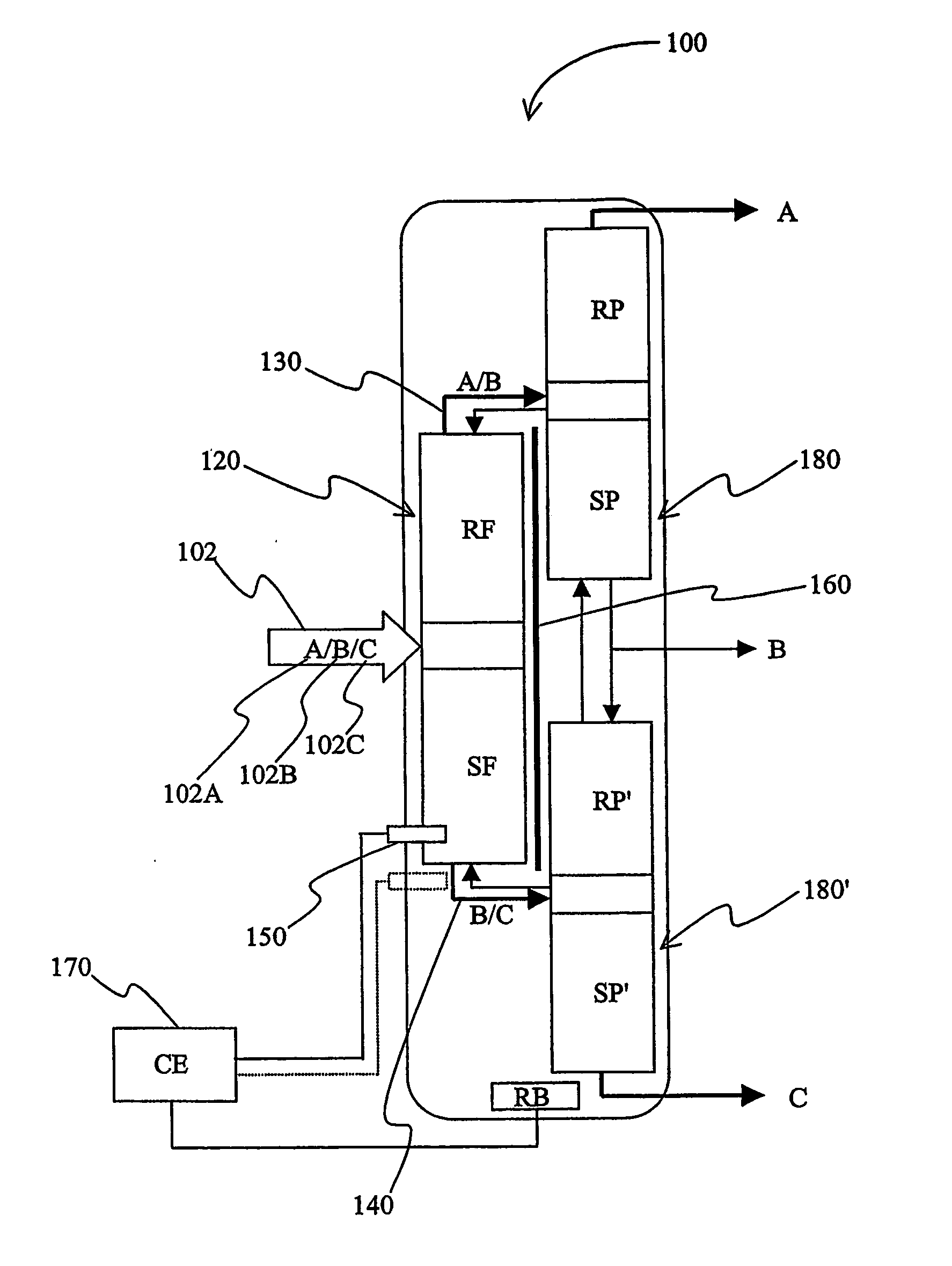
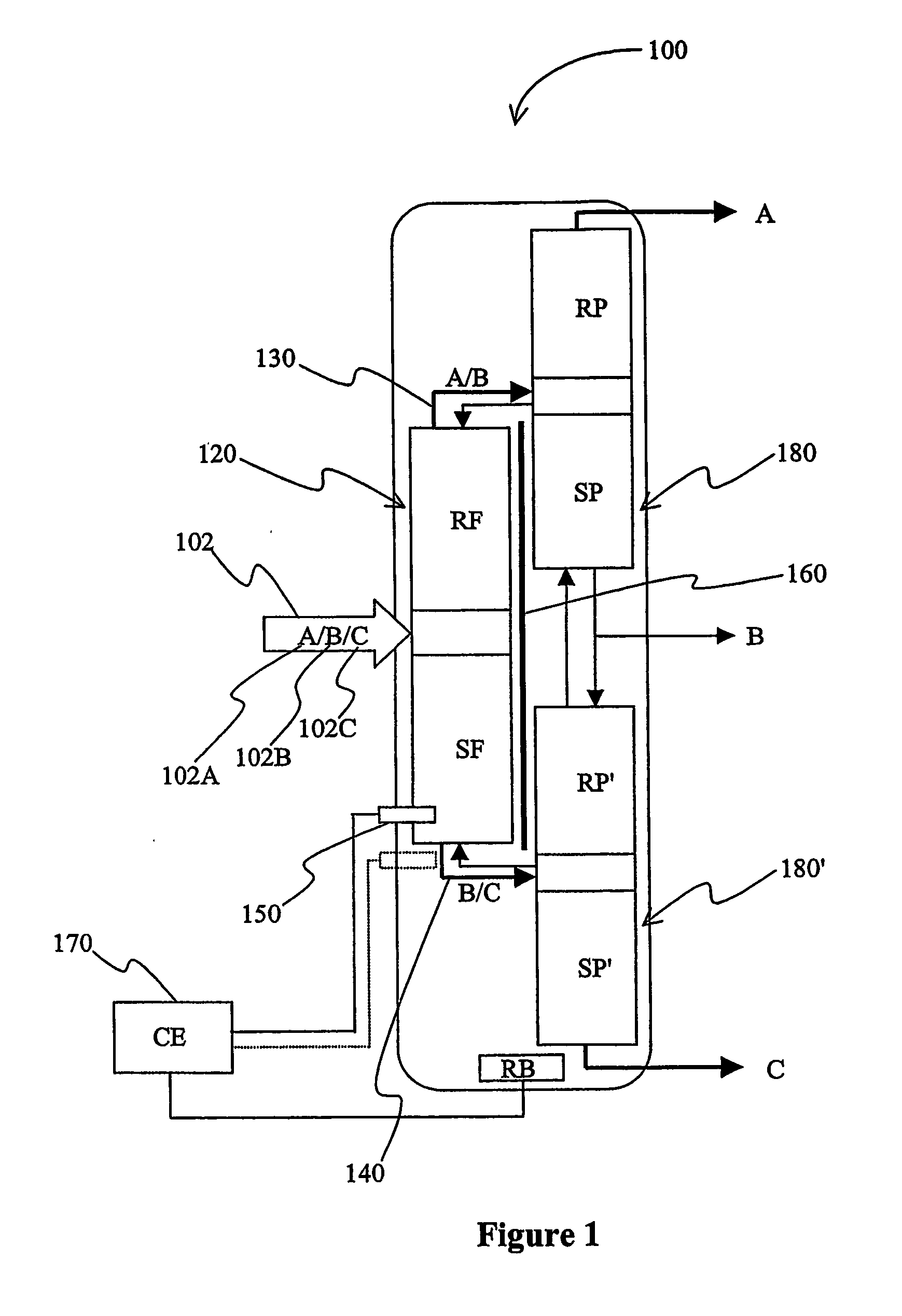
[0015] As used herein, the term “divided wall column” or “dividing wall column” refers to a distillation system for one or more multi-component feeds in which at least two, and more typically three thermally coupled distillation columns are disposed in a common shell and separate the multi-component feed into at least one light, at least one intermediate, and at least one heavy boiling fraction. Exemplary divided wall columns are described, for example, in U.S. Pat. No. 4,230,533 to Girox, or in a presentation by Becker et al. [The world's larges partitioned column with trays. Linde Reports on Science and Technology 62 (2000), pages 42-48] (infra).

[0016] The inventors have discovered that improved control over traffic of the light, intermediate, and / or heavy boiling fraction in a divided wall column (DWC) can be achieved by thermally coupling a differential vapor pressure (DVP) cell to the divided wall column. More specifically, the inventors contemplate that descent of excess ligh...


PUM


Abstract

A differential vapor pressure (DVP) cell (150) is disposed in a divided wall column (100) that receives a feed comprising a first (102A), second (102B), third (102C) component. A separation section (120) on the feed side of the divided wall column separates the feed in a vapor comprising the first and second component, and a liquid comprising the second and third component. The DVP cell is disposed in the divided wall column at a level below the point where the feed enters the column, and the DVP cell measures the concentration of the first component.

Description

FIELD OF THE INVENTION [0001] The field of the invention is monitoring and flow control of feed components in distillation columns, and especially in divided wall columns. BACKGROUND OF THE INVENTION [0002] Thermally coupled distillation and the concept of carrying out such a distillation in a single column with a dividing wall separating the feed side from the side product side have been known for a long time (see e.g., U.S. Pat. No. 2,295,256 to Brugma, U.S. Pat. No. 2,471,134 to Wright, and the paper by Triantafyllou and Smith [Design and optimization of fully thermally coupled distillation columns. Trans I. Chem. E, Vol 70, Part A (1992), pages 118-132]). [0003] Divided wall columns typically have a configuration in which a vertical baffle in the middle section of the column separates the feed point from the point at which the intermediate boiling point product is withdrawn. In this way, the quantities of both light and heavy components in the feed reaching the side draw may be ...

Claims


Application Information

Patent Timeline
IPC IPC(8): B01D3/42B01D3/14C10G7/00
CPCB01D3/14B01D3/141B01D3/4211C10G7/00Y10S203/19Y10S203/20
Inventor KISTER, HENRYSTUPIN, WALT
Owner FLUOR TECH CORP
Learn More