Device for packaging and dispensing a product

a technology for packaging and products, applied in the direction of liquid/fluent solid measurement, single-unit apparatus, instruments, etc., can solve the problems of reducing the risk of actuating the pump plunger when assembling the device on the container, limiting the risk of actuating the pump plunger when assembling the device, and the type of device does not permit the use of different pumps. , to achieve the effect of reducing or limiting the risk of actuating, limiting the risk of produ

Inactive Publication Date: 2006-06-29
LOREAL SA
View PDF9 Cites 41 Cited by
  • Summary
  • Abstract
  • Description
  • Claims
  • Application Information

AI Technical Summary

Benefits of technology

[0011] It is a particular object of an embodiment of the present invention to provide a packaging and dispensing device that includes a dispensing element with a reduced risk of being actuated during assembly of the diffuser on the container.
[0037] The trigger can be pivoted on the mounting member, in particular by a first end of the trigger. For this purpose, the first end of the trigger can include two lateral holes designed to delineate a pivot axis, for example an axis substantially perpendicular to the lengthwise axis of the trigger. The two holes can be configured to receive two protruberances provided on the mounting member thereby facilitating a pivoting movement of the trigger relative to the mounting member about the pivot axis.

Problems solved by technology

However, when the diffuser is placed on the actuating rod, the rod may be forced substantially downward and product can escape from the container.
Such devices are directly attached to the container so that the risk of actuating the pump plunger when assembling these devices on their container is limited.
However, this type of device does not permit the use of different pumps, when it is desired for example to dispense a different dose of product, unless the whole of the head assembly is changed.
Moreover, the triggers are of limited aesthetic appeal and do not offer a very wide choice of designs.
Such a device can therefore be inadvertently actuated before a first use.

Method used


Image

  • Device for packaging and dispensing a product
  • Device for packaging and dispensing a product
  • Device for packaging and dispensing a product

Examples


Embodiment Construction

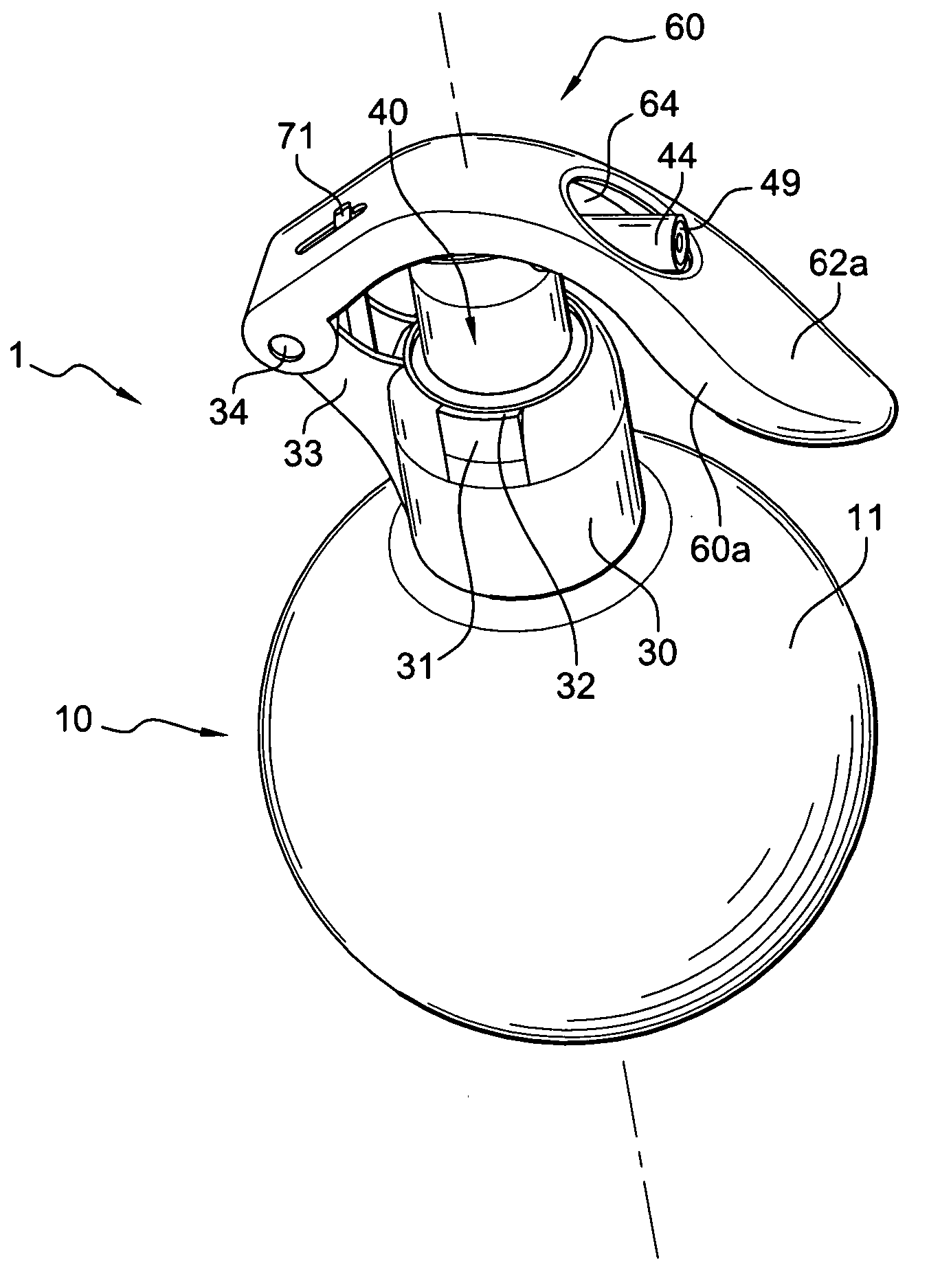
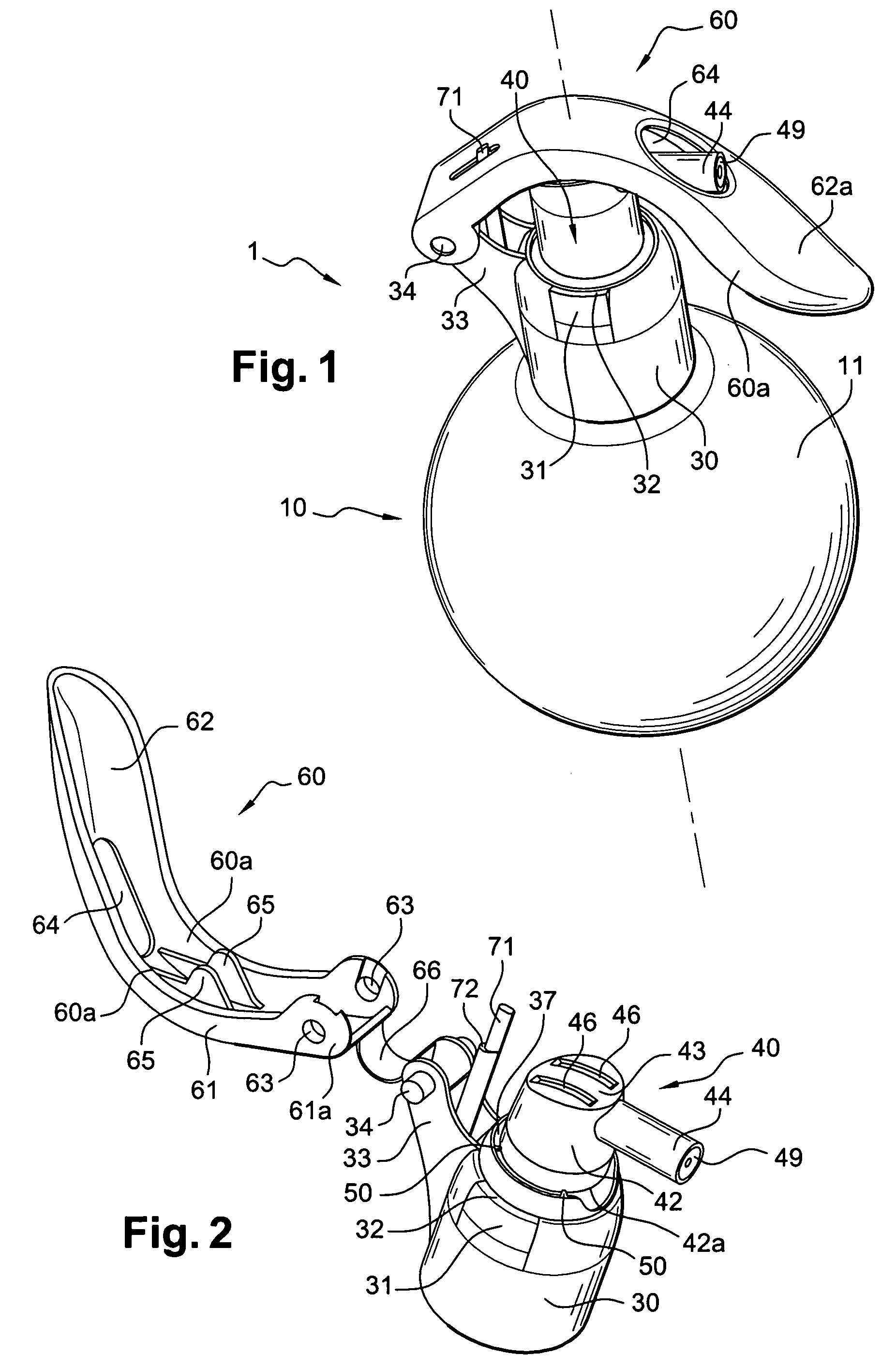
[0053] The device 1 includes a container 10, made in a thermoplastic material for example. Other material can be used to make the container, and in particular tin plate or aluminium. The container 10 includes a body 11, for example generally spherical in shape and including an open neck 12 wherein a pump 20 of lengthwise axis X is mounted using a fixing skirt 23 attached to the outer wall of the neck 12. The container can alternatively have any other shape, in particular a cylindrical shape.

[0054] The pump 20, which is not shown in detail in the figures, can be a standard pump, preferably of the pre-compression type. The pump includes a plunger of which the movement inside the pump body, in one direction, causes the product to be expelled under pressure, and in the other direction, causes product to be drawn into the pump body. Generally, the plunger is held in a position corresponding to the maximum volume of the pumping chamber using a spring. As can be seen in FIGS. 8 to 10, the...


PUM


Abstract

A device for packaging and dispensing a product, such as a cosmetic product. The device includes a container fitted with a dispensing element designed to facilitate discharge of the product from the container, and a dispensing head surmounting the container. The dispensing head includes a mounting member configured to attach to the dispensing element or the container. The dispensing head also includes a diffuser fitted with a dispensing orifice configured to move and actuate the dispensing element so as to cause the product to be released. The diffuser is connected, before a first actuation of the dispensing element, to the mounting member by at least one bridge of material in a position such that the diffuser is not in fluid communication with the dispensing element, the bridge of material being breakable upon first actuation so as to enable fluid engagement of the dispensing element with the diffuser.

Description

CROSS-REFERENCE TO RELATED APPLICATIONS [0001] This application claims priority to French Application No. 0452792, filed Nov. 29, 2004 and U.S. Provisional Application No. 60 / 634,288, filed Dec. 9, 2004, the entire content of both of which is hereby incorporated by reference.BACKGROUND OF THE INVENTION [0002] 1. Field of the Invention [0003] The invention discloses a device for packaging and dispensing a product, for example a cosmetic product. Such a product can be dispensed for example in the form of a cream, a gel, a foam or a spray. [0004] 2. Discussion of the Background [0005] The expression “cosmetic product” is understood to mean a product such as defined in Council Directive 93 / 35 / EEC dated 14th Jun. 1993, amending Directive 76 / 768 / EEC for the sixth time. [0006] Generally, a packaging and dispensing device can include a container holding the product to be dispensed fitted with a dispensing element. Such a dispensing element can be a pump or a valve which is surmounted by a d...

Claims


Application Information

Patent Timeline
Patent Type & Authority Applications(United States)
IPC IPC(8): G01F11/06B65D88/54G01F11/30
CPCB05B11/3057B05B11/3059B65D83/206B65D83/22B05B11/1057B05B11/1059
Inventor LASSERRE, PIERRE-ANDRESANCHEZ, MARCEL
Owner LOREAL SA
Why Eureka
Try Eureka