
Power driven bone crusher and method for bone crushing

a technology of power driven bone crusher and bone crusher, which is applied in the direction of solid separation, medical science, prosthesis, etc., can solve the problems of large existing bone mill, cumbersome use and cleaning of expensive devices, and inability to immediately provide bone mills,

Inactive Publication Date: 2006-06-29
MEDICAL INNOVATORS
View PDF15 Cites 33 Cited by
  • Summary
  • Abstract
  • Description
  • Claims
  • Application Information

AI Technical Summary

Benefits of technology

Reduces the cost and time required for orthopedic procedures, increases surgical efficiency, and ensures uniform bone particle sizes, minimizing contamination risks.

Problems solved by technology

Existing bone mills are large, expensive devices which are cumbersome to use and clean and further require re-sterilization at the end of each procedure.
Such re-sterilization takes the form of expensive and time consuming gas sterilization or autoclave sterilization.
When using an autoclave sterilization process, the bone mills can be sterilized and available for reuse in less than a 24-hour period, however, the bone mills are not immediately available.
The resulting period required to re-sterilize the bone mills nevertheless increases the time which necessarily passes between procedures, thereby decreasing operating room and surgical efficiency.
The blade porosity hampers the effectiveness of the cleaning process, which furthers the possibility of contamination during subsequent use of the bone mill.
Additionally, existing mills may only have the capability to produce a single size of crushed bone particles.
As such, a surgical suite needs to have multiple devices to provide crushed bone at different sizes, which greatly increases the cost of having bone-milling capabilities.
Otherwise, a surgeon is disadvantageously forced to use crushed bone having a size either too large or too small for a particular surgical procedure, resulting in potential difficulties during an orthopedic procedure.

Method used


Image

  • Power driven bone crusher and method for bone crushing
  • Power driven bone crusher and method for bone crushing
  • Power driven bone crusher and method for bone crushing

Examples


Embodiment Construction

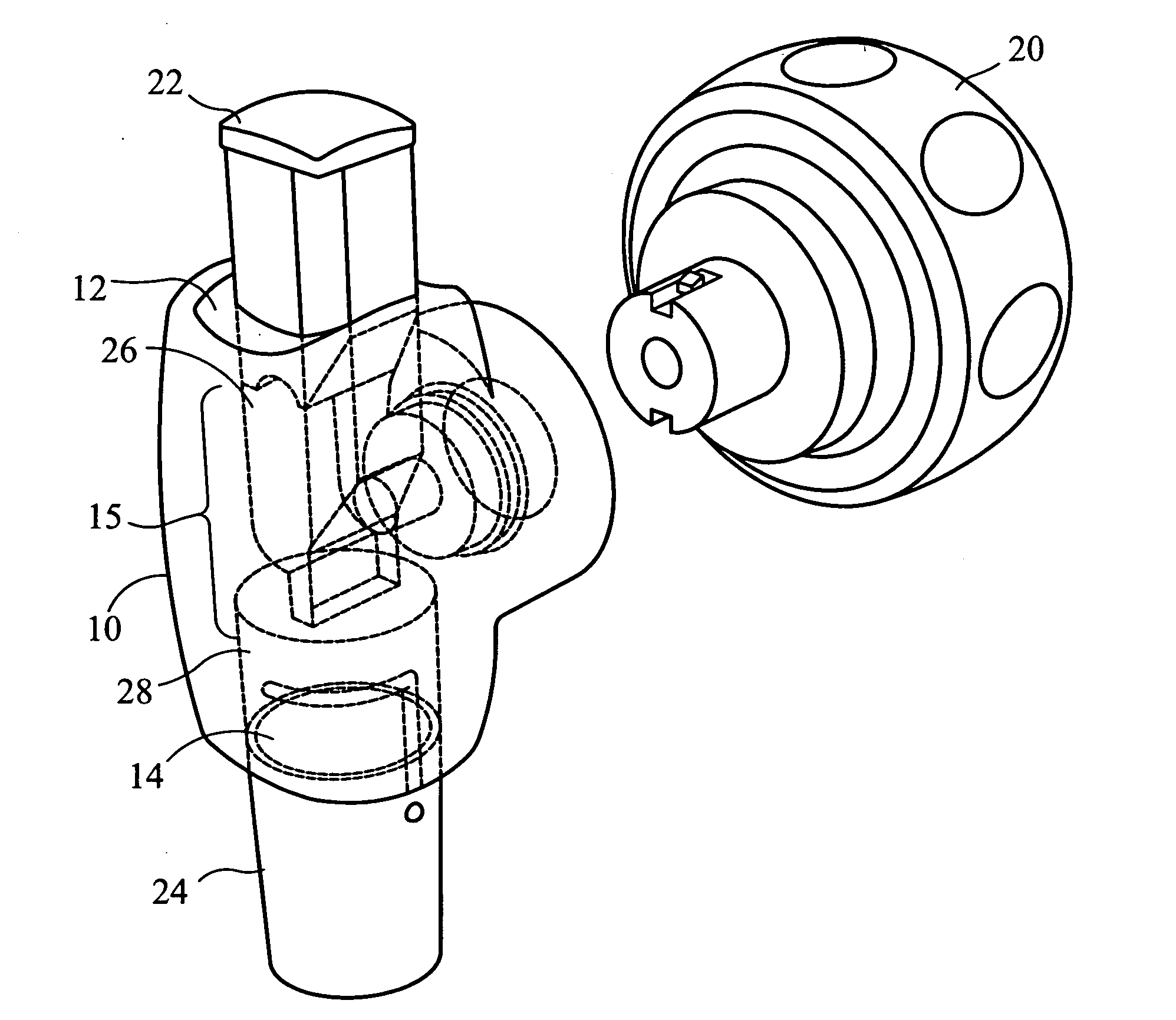
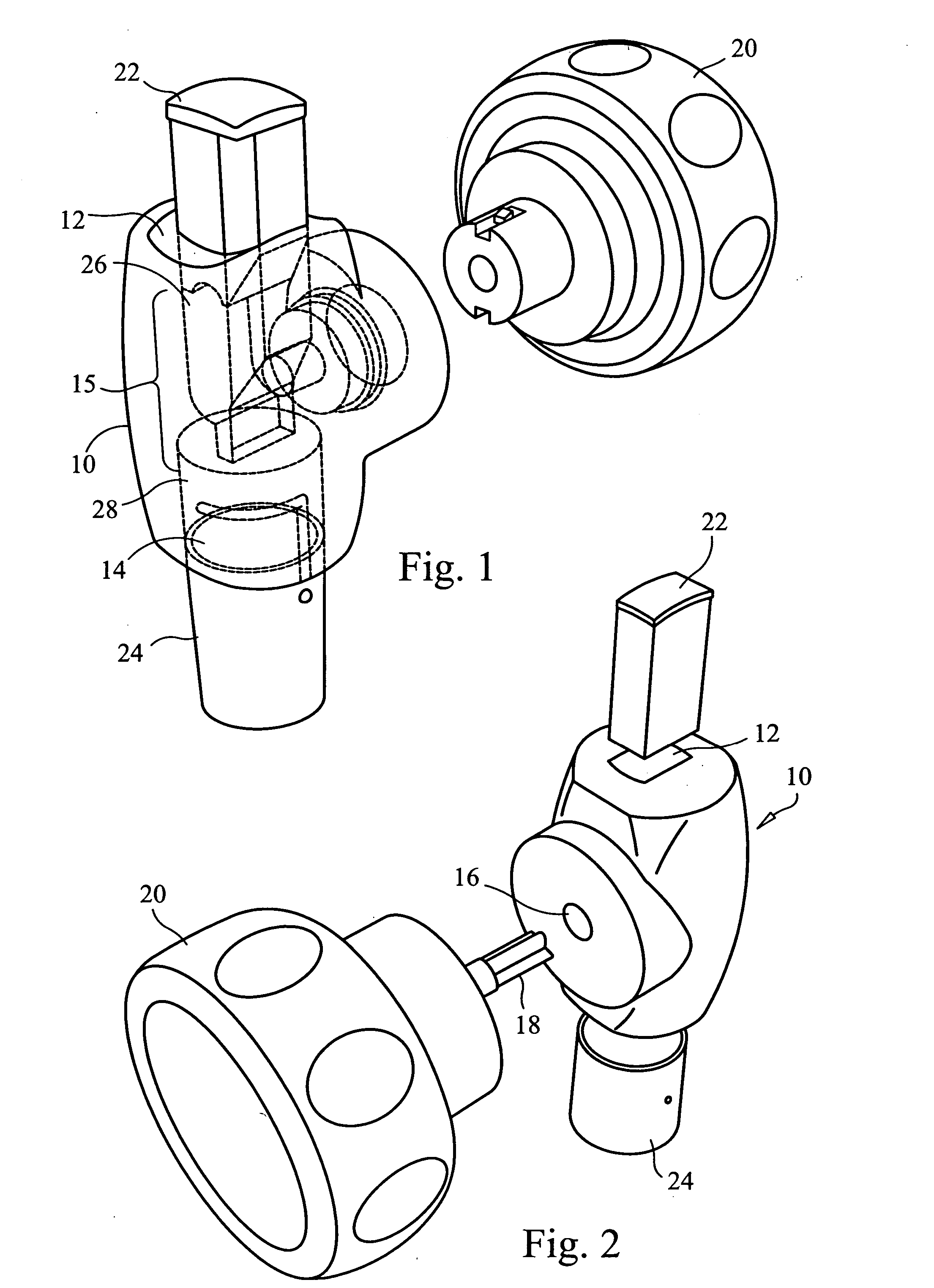
[0041] The present invention provides a disposable, hand-operated bone mill that accommodates cutting plates to produce bone chips of a selected size based on a blade installed in the mill body 10. Referring now to FIG. 1, an exemplary embodiment of the present invention includes a bone mill having a mill body 10 that defines a first opening 12, a second opening 14, and a linear passage 15 that extends from the first opening 12 to the second opening 14. The mill body 10 further includes a rotatable cutting member 18 coupled to an actuator element 20, as shown in FIG. 2. Further, the mill body 10 can include a third opening 16 through which the rotatable cutting member 18 couples to the actuator element 20. The first opening 12 can be adapted to receive a plunger 22, and a receptacle 24 can be removably coupled to the second opening 14.

[0042] The first opening 12 provides an access area into which a suitably sized bone portion can be inserted for milling. First opening 12 can be of ...


PUM


Abstract

An apparatus for bone milling includes a housing defining a first opening, a second opening opposite the first opening, and a linear passage from the first opening to the second opening. The linear passage has a first surface with third opening there through and a second surface transverse to the first surface. A rotatable cutting member is insertable through the third opening to partially block the linear passage. The rotatable cutting member is positioned at a distance from the second surface of the linear passage corresponding to a predetermined bone chip size.

Description

CROSS-REFERENCE TO RELATED APPLICATION [0001] This application is a Continuation-in-Part of and claims priority to U.S. Continuation-in-Part Patent Application Ser. No. 11 / 051,882, filed Feb. 4, 2005, entitled BONE CRUSHER AND METHOD FOR BONE CRUSHING, which Application claims priority from U.S. Utility Patent Application Ser. No. 10 / 961,573, filed Oct. 08, 2004, entitled BONE CRUSHER AND METHOD FOR BONE CRUSHING, which application is related to and claims priority to U.S. Provisional Patent Application Ser. No. 60 / 542,209, filed Feb. 05, 2004, entitled BONE CRUSHER AND METHOD THEREFORE, the entirety of all which are incorporated herein by reference.STATEMENT REGARDING FEDERALLY SPONSORED RESEARCH OR DEVELOPMENT [0002] n / a FIELD OF THE INVENTION [0003] The present invention relates to an orthopedic medical device and method, in particular to a method and device for bone cutting for use during orthopedic surgery. BACKGROUND OF THE INVENTION [0004] Orthopedic surgery often requires th...

Claims


Application Information

Patent Timeline
Patent Type & Authority Applications(United States)
IPC IPC(8): B02C17/02A61F2/30A61F2/46B02C19/00
CPCA61F2/4644A61F2002/30604A61F2002/4645A61F2002/469B02C19/0056
Inventor HAY, JAMES SCOTTCARNATION, JAMESWIEDER, BRIANPANTHER, ADRIANSINGH, RYAN
Owner MEDICAL INNOVATORS
Learn More