Drag control member attachment structure

a technology of attachment structure and control member, which is applied in the direction of fishing, applications, reels, etc., can solve the problems of difficult to form a recessed part with a precise hexagon, and achieve the effect of simplifying the cam structure, reducing the variation of contact parts, and stable number of contact parts

Active Publication Date: 2006-06-29
SHIMANO INC
View PDF3 Cites 33 Cited by
  • Summary
  • Abstract
  • Description
  • Claims
  • Application Information

AI Technical Summary

Benefits of technology

[0010] It is difficult to form a recessed part with a precise hexagon because the hexagonal recessed section is formed by a tool that is usually in a cylindrical shape. Accordingly, in the present invention, the first and fourth inner peripheries of the hexagonal recessed section are separated away from the outer peripheral surface of the hexagonal guiding portion. Thus, these parts do not serve to stop rotation. In addition, the second and fifth inner peripheries adjacent to the first and the fourth inner peripheries define the first and second contact parts on the first and fourth inner periphery sides that are in contact with the first and third parts of the second and fifth outer peripheries. The second and fifth inner peripheries define the first and second separated part on the third and sixth inner peripheries sides that are separated away from the second and fifth outer peripheries. The third and sixth inner peripheries adjacent to the second and fifth inner peripheries are in contact with third and sixth inner peripheries. In this case, the first and fourth inner peripheries are separated away from the first and second outer peripheries and the first and second separated parts are provided on the second and fifth inner peripheries. Thus, even if a cylindrical tool is used, such a tool can be relieved to these parts. The first and second contact parts and the third and sixth inner peripheries can be precisely formed along the first and third parts of the second and fifth outer peripheries and the third and sixth outer peripheries of the hexagon by a machining process. Additionally, the first and second contact parts are disposed on the upstream side of the pivoting direction where the larger force is applied on the guiding portion. As a result, when the drag control member is operated to pivot in this direction, the number of contact parts that contact the guiding portion is greater than the number of contact parts in the case of the opposite direction.
[0017] Specifically, when the drag control member is operated in the direction that increases the drag force, total four parts that include the first and second contact parts and two parts of the third and sixth inner peripheries on the second and fifth inner periphery sides come in contact with the outer peripheral surface of the guiding portion. On the other hand, when it is operated to pivot in the opposite direction, only two parts of the third and sixth inner peripheries on the fourth and first inner periphery sides come in contact with the outer peripheral surface of the guiding portion. Therefore, the number of the contact parts is stable. Thus, it is possible to reduce variation of the contact parts between the hexagonal guiding portion and the reel unit.

Problems solved by technology

It is difficult to form a recessed part with a precise hexagon because the hexagonal recessed section is formed by a tool that is usually in a cylindrical shape.
Thus, these parts do not serve to stop rotation.

Method used


Image

  • Drag control member attachment structure
  • Drag control member attachment structure
  • Drag control member attachment structure

Examples


Embodiment Construction

[0033] A selected embodiment of the present invention will now be explained with reference to the drawings. It will be apparent to those skilled in the art from this disclosure that the following description of the embodiment of the present invention is provided for illustration only and not for the purpose of limiting the invention as defined by the appended claims and their equivalents.

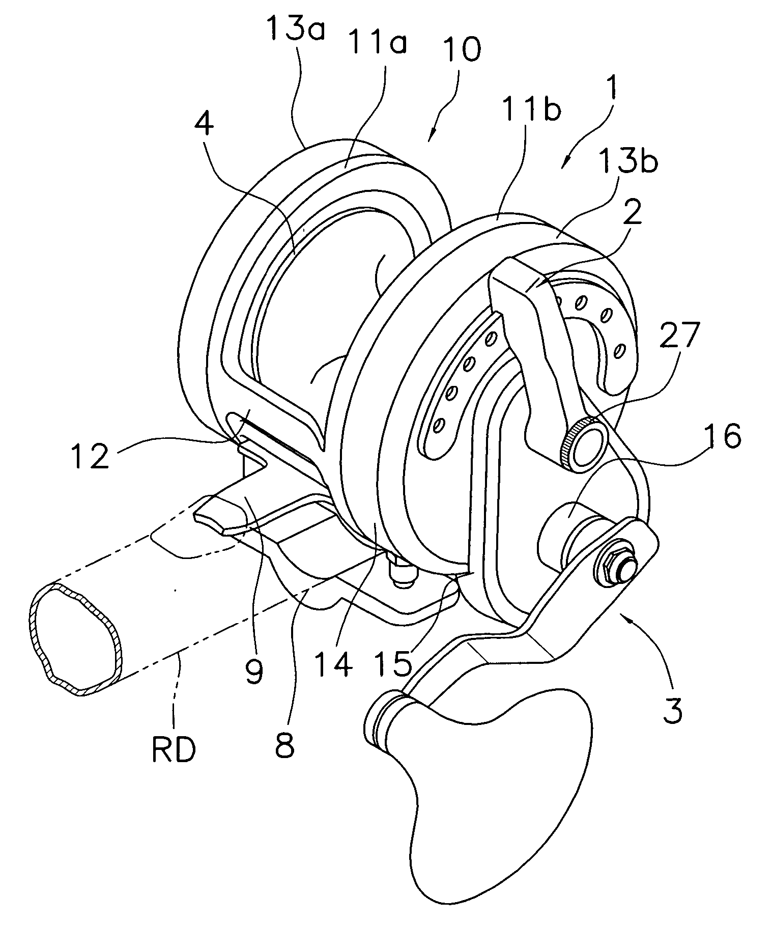
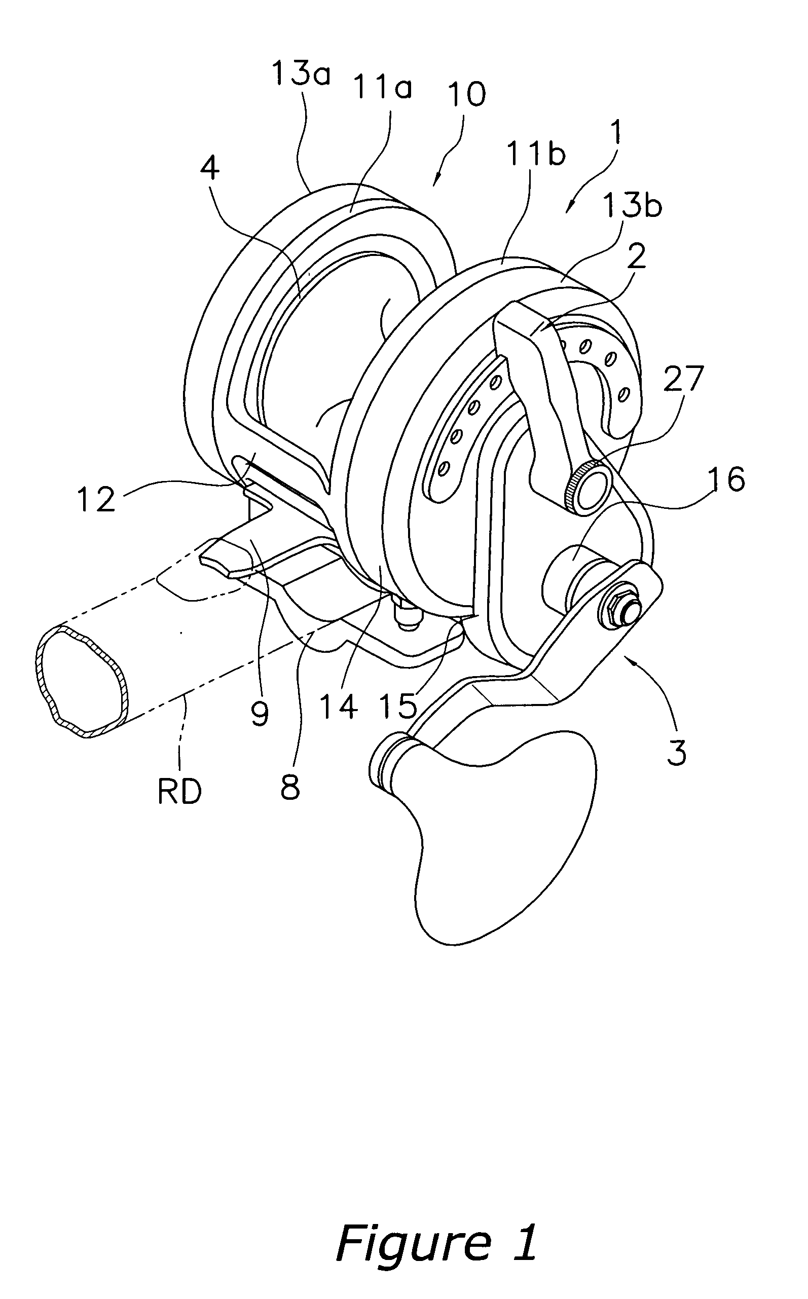
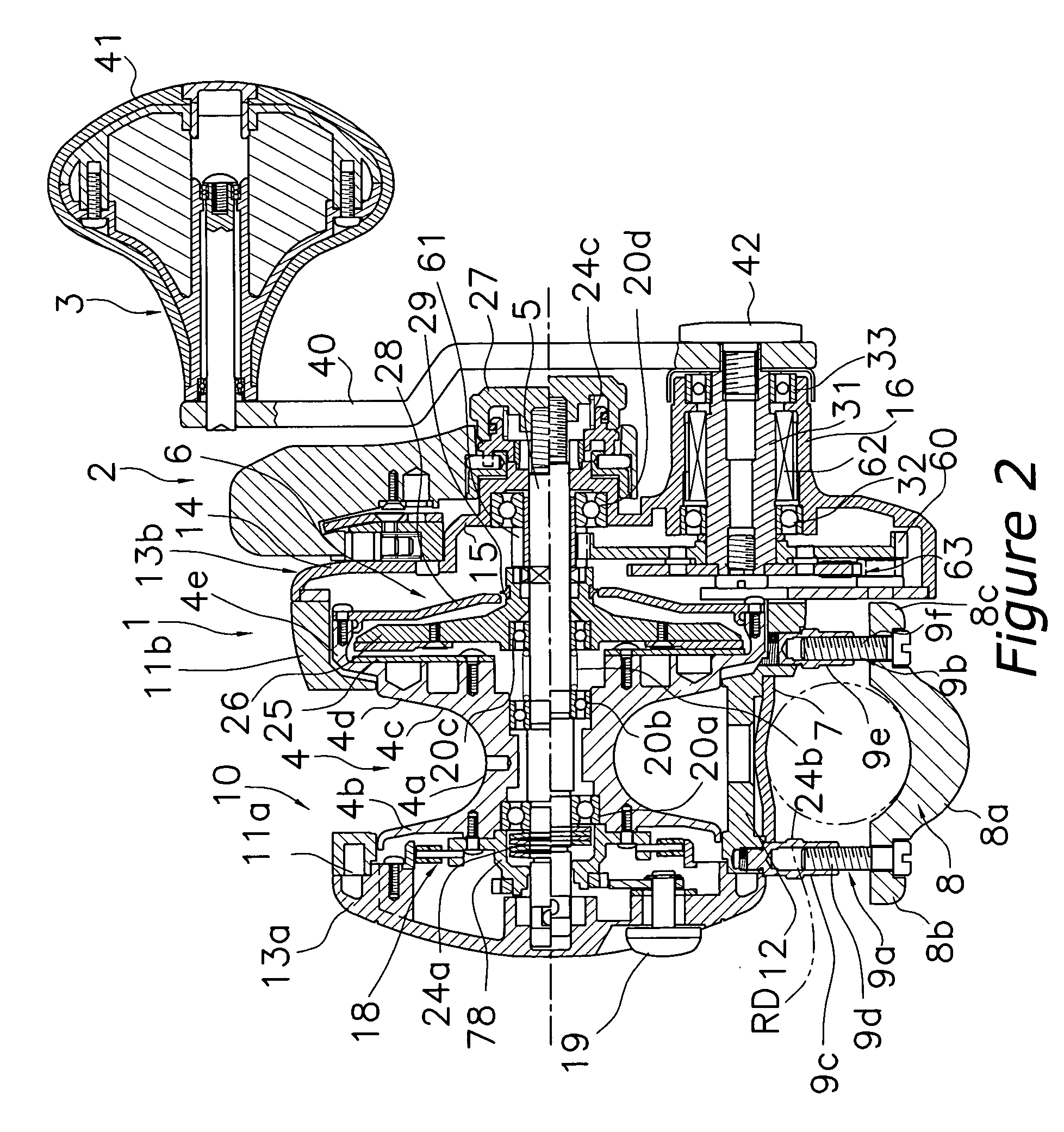
[0034] Referring initially to FIGS. 1 and 2, a dual-bearing reel is illustrated in accordance with a first embodiment of the present invention. The dual-bearing reel is a medium sized lever-drag type reel and includes a reel unit 1, a drag control member 2, a handle 3 and a spool 4. The drag control member 2 is pivotally provided on a side of the reel unit 1. The handle 3 is rotatably supported by the reel unit 1 below the drag control member 2. The spool 4 is provided inside the reel unit 1.

[0035] The reel unit 1 has a frame 10 and first and second side covers 13a and 13b that cover sides of the ...


PUM


Abstract

A drag control member attachment structure for a lever-drag type reel has a first cam member, a second cam member, a guiding portion, a guide fastening portion and a pivot support portion. The pivot support portion is disposed on an outer periphery side of the guide fastening portion. The second cam member engages with the first cam member and moves in a pivot axis direction in response to pivoting of the first cam member. The guiding portion has a cylindrical section and a hexagonal section that non-rotatably and movably guides the second cam member in the pivot axis direction. The guide fastening portion includes a hexagonal recessed section that is disposed on a side of the reel unit and receives the hexagonal section. The guide fastening portion further includes a through hole that receives the cylindrical section.

Description

CROSS-REFERENCE TO RELATED APPLICATIONS [0001] This application claims priority to Japanese Patent Application Nos. 2004-377732 and 2005-68012. The entire disclosures of Japanese Patent Application Nos. 2004-377732 and 2005-68012 are hereby incorporated herein by reference. BACKGROUND OF THE INVENTION [0002] 1. Field of the Invention [0003] The present invention generally relates to an attachment structure. More specifically, the present invention relates to an attachment structure of a drag control member of a lever drag reel that adjusts a drag force of a drag mechanism. [0004] 2. Background Information [0005] A lever-drag reel is known to have a reel that is capable of adjusting drag force by moving a spool shaft in an axial direction by a drag control member that is pivotably attached on the spool shaft. (See, for example, Japanese Publication No. H11-9157.) A base end of this of type drag control member is pivotably supported by a pivot support portion that is formed in a cover...

Claims


Application Information

Patent Timeline
Patent Type & Authority Applications(United States)
IPC IPC(8): A01K89/02
CPCA01K89/033A01K89/015A01K89/0155
Inventor IKUTA, TEKESHIKAWASAKI, KEN'ICHI
Owner SHIMANO INC
Why Eureka
Try Eureka